Cybex 750C/750R Owner’s Manual
Assembly and Setup
Page 2–12
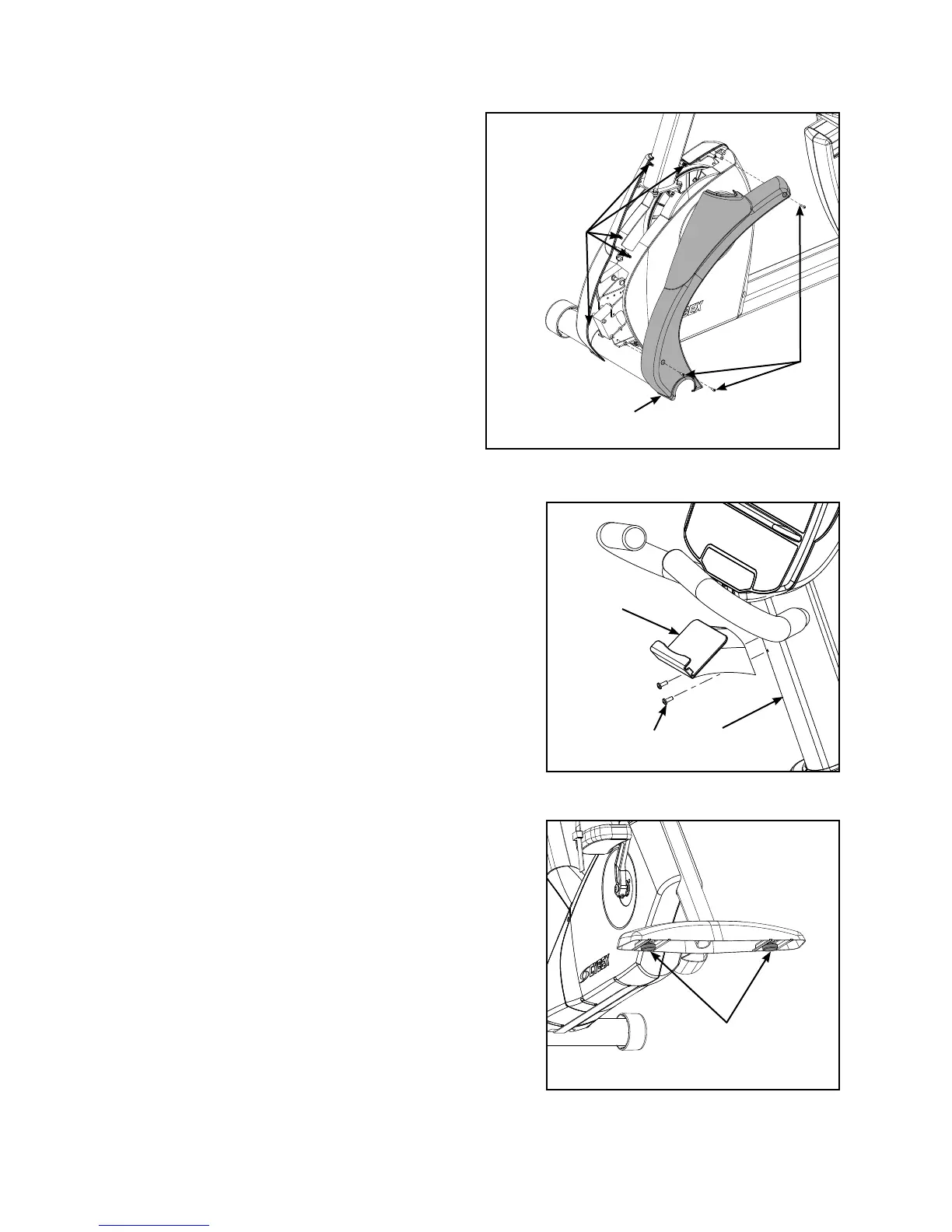
C. Locate and place the front left cover (#3)
on the front of the unit as shown in
Figure 7.
D. Using a Phillips screwdriver, secure with
three screws 8-16 x .50” (#13). See
Figure 7.
6. Install the accessory tray.
A. Locate the accessory tray (#6). See
Figure 8.
B. Using a Phillips screwdriver, remove the
two screws in the console assembly (#2).
C. Using a Phillips screwdriver, secure the
accessory tray (#6) to the console
assembly (#2) with the two screws
removed in step 6B.
7. Level the unit.
A. Confirm that the unit is on a level surface. If not,
use a 9/16” open-end wrench to adjust the leveling
feet up or down. See Figure 9.
8. Visually inspect the unit.
A. Carefully examine the unit to ensure that the
assembly is correct and complete.
B. Proceed to Testing the Operation section.
Figure 8
Figure 7
#13
#3
Plastic
Connectors
Screws (2)
Figure 9
Leveling Feet
#6
#2