Assembly
Page 5-10
Cybex Free Weight Owner’s Manual
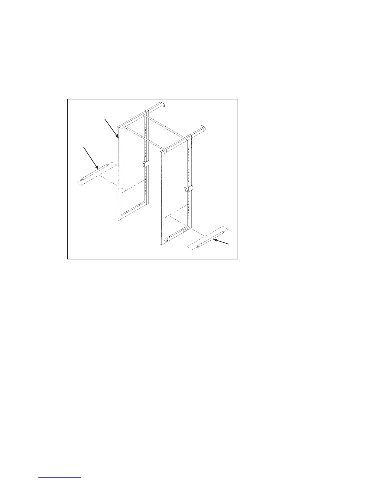
6. Attach adjusting bars (see steps 6A and 6C and Figure 7).
Locate both adjusting bars (#3).
Position adjusting bar (#3) in Power Cage and align holes. See Figure 7.
Repeat Step 6B to attach other side.
A.
B.
C.
7. Secure Power Cage to attachment (see steps 7A - 7K and Figures 8 - 11).
Locate right side attachment (#20), one center brace (#21), one bottom support bar (#13),
four plastic inserts 1.19 Dia. (#6), two spacer plates (#14), two BHSCS .50-13 x 1.00 (#5),
two washers .50 (#4), eight lockwashers .50 (#18), six SHCS .50-13 x 1.00 (#16) and eight
hex nuts .50-13 (#15)
Position right side attachment (#20) up to Power Cage. Align the two holes.
Attach right side attachment (#20) to Power Cage with two SHCS .50-13 x 1.00, two lockwashers
.50 and two hex nuts .50-13. Do not tighten hardware at this time. See Figure 8.
A.
B.
C.
Figure 7
3
3
Power
Cage
 Loading...