EasyManuals Logo

CYG PRS-7910 User Manual

Default Icon
75 pages
To Next Page IconTo Next Page
To Previous Page IconTo Previous Page
Page #29 background imageLoading...
Page #29 background image
PRS-7910
PRS-7910 15
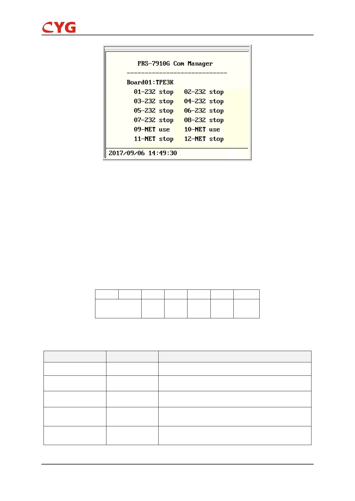
Figure 6.2.1 HMI view (Virtual LCD tool)
6.3 PWR Module (Power Supply)
The PWR module is a DC/DC or AC/DC converter with electrical insulation between the input and
output. It has an input voltage range as described in the chapter 2. The tolerance of the output
voltage for the electronic components is continuously monitored.
The use of an external miniature circuit breaker is recommended. The miniature circuit breaker
must be in the on position when the device is in operation and in the off position when the device is
in cold reserve. A 6-pin connector is fixed on the PWR module. The pin definition of the
connector is described as below.
1
2
3
4
5
6
7
Power supply -
normally closed
L/+
N/-
GND
Figure 6.3.1 PWR terminals
Table 6.3.1 Symbol description
Pin No.
Symbol
Description
01
Indication of power failure alarm 1
02
Indication of power failure alarm 2
03
NC
Not used
04
+/L
Positive pole of power supply for device/Live wire for AC
power
05
-/N
Negative pole of power supply for device/Neutral line for AC
power

Table of Contents

Questions and Answers:

Question and Answer IconNeed help?

Do you have a question about the CYG PRS-7910 and is the answer not in the manual?

CYG PRS-7910 Specifications

General IconGeneral
BrandCYG
ModelPRS-7910
CategoryNetwork Hardware
LanguageEnglish