PRS-7910
54 PRS-7910
3. Air must be allowed to circulate freely around the equipment.
The equipment can in principle be mounted in any attitude, but it is normally mounted vertically
(visibility of markings).
NOTICE!
Excessively high temperature can appreciably reduce the operating life of this device.
11.6 Mechanical Installation
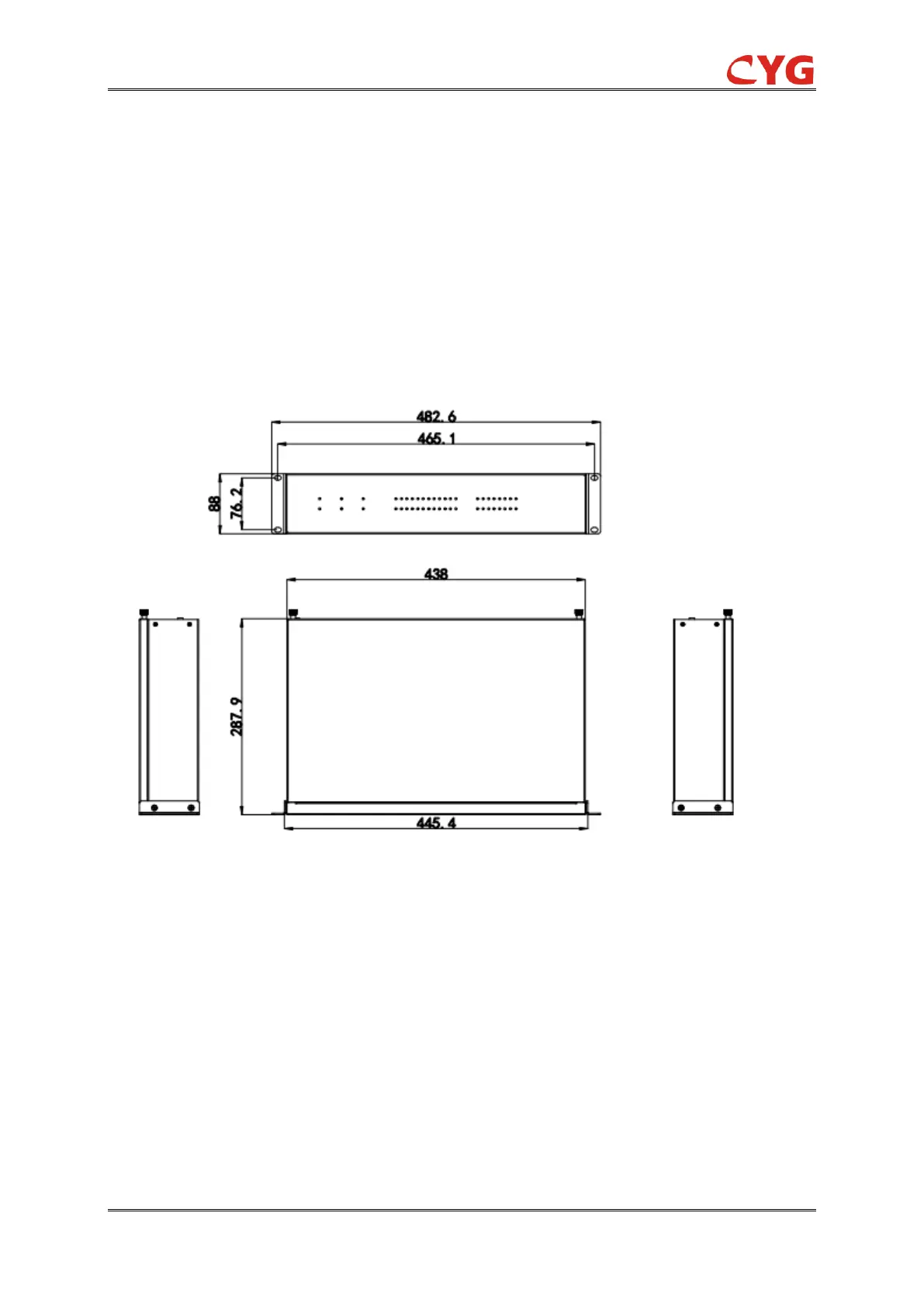
This relay is made of a single layer 2U height 19" chassis with 8 connectors on its rear panel. The
following figure shows the dimensions of this relay for reference in mounting.
Figure 11.6.1 Dimensions of this relay (2U 19" rack) and the cut-out in the cubicle (unit: mm)
NOTICE!
It is necessary to leave enough space top and bottom of the cut-out in the cubicle for
heat emission of this relay.
As mentioned in Chapter 6, up to eight modules are installed in the enclosure of this relay, and
these modules must be plugged into the proper slots of this relay respectively. The safety
instructions must be abided by when installing the boards, please see Section 11.2 for the details.
In the case of equipment supplied in cubicles, place the cubicles on the foundations that have
been prepared. Take care while doing so not to jam or otherwise damage any of the cables that
have already been installed. Secure the cubicles to the foundations.
 Loading...