1. Connect DC Power
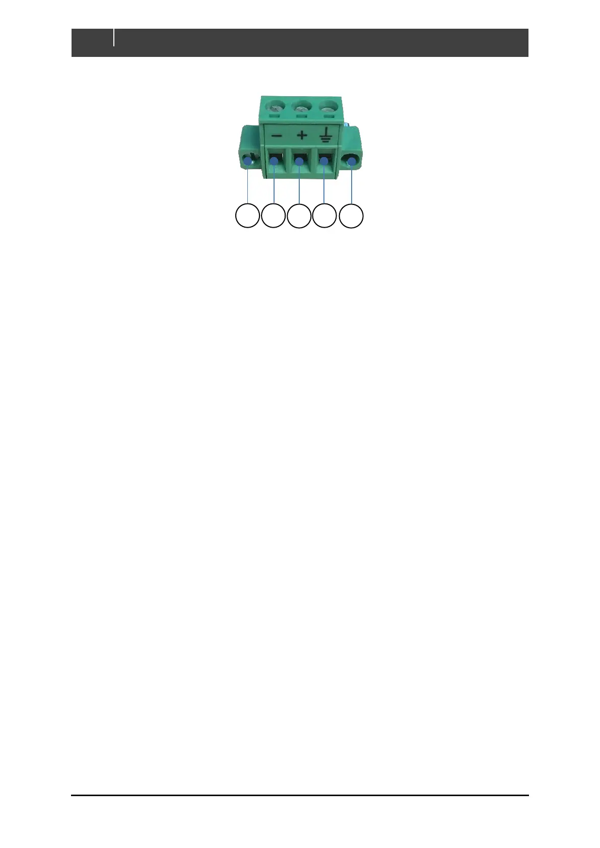
Figure 12. DC Connector Pinout
1. DC Negative Connection - Connect appropriately sized negative wire from – position of
power connector to battery negative terminal. Ensure conductor is secured by tightening
screw.
2. DC Positive Connection - Connect appropriately sized positive wire from + position of
power connector to battery positive terminal through a 3A fuse. Secure conductor in place
by tightening screw.
3. Shield Connection (Optional) – Connect shield to the vessel or vehicles chassis/ground
ONLY if touch screen interference is observed.
Note: Frequencies emitted from some electrical equipment can cause interference with
the display’s touch screen. If issues are experienced with touchscreen performance firstly
try recalibrating the screen via the displays Settings page. If the performance does not
improve then the shield cable should be connected to chassis/ground.
4. Ensure power supply to Touch 7 is disconnected or switched off initially, then insert
connector in to Touch 7 power socket and lock connector in place by tightening locking
screws.
2. Connect Ethernet to Router (Optional)
Run an ethernet cable from the Ethernet port on the Touch 7 to an ethernet port on the router, only if
the Touch 7 will be configured in Client Mode Wired. Refer to 2.5 for definitions of the supported
network configurations.
3. Connect NMEA 2000 Network
Run supplied NMEA2000 1M Drop cable from NMEA2000 port on Touch 7 to NMEA2000 backbone.