D-Link Services Router 1
ENGLISH
About This Guide
This guide gives step by step instructions for
setting up D-Link DSR-500/1000 Services Router.
Please note that the model you have purchased
may appear slightly different from those shown in
the illustrations.
Unpacking the Product
Open the shipping carton and carefully unpack its
contents. Please consult the packing list located
in following information to make sure all items are
present and undamaged. If any item is missing
or damaged, please contact your local D-Link
reseller for replacement.
- One (1) DSR-500/1000 Services Router
Appliance.
- One (1) Power adapter
- One (1) Console Cable (RJ45-to-DB9 Cable)
- One (1) Ethernet (CAT5 UTP/Straight Through)
Cable
- One (1) Reference CD (CD-ROM containing
product documentation in PDF format)
- Two (2) Rack Mounting Brackets
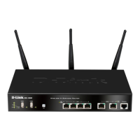
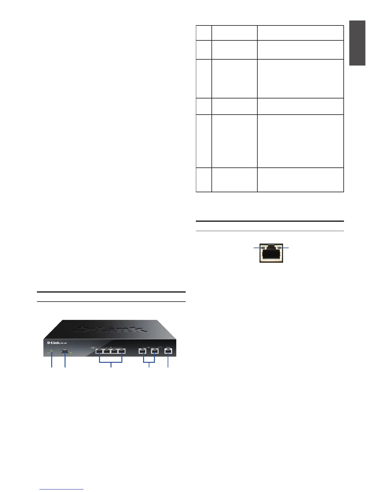
Item Feature Description
A LED Power LED: Indicates the Services
Router is powered on.
B USB Port It can support various USB 1.1 or
2.0 devices below:
1. Flash Disk or Hard Disk for
network sharing.
2. 3G Adaptor for WAN redundant
3. Printer
C Gigabit LAN port
(1-4)
Connect Ethernet devices, such as
computers, switches and hubs.
D Gigabit WAN port
(1-2)
Two auto MDI/MDIX WAN ports
are the connection for the Ethernet
cable to the cable or DSL modem.
The WAN2 port is a congurable
port which can support WAN2 or
DMZ port for dual WAN connec-
tions or internal Server Farm
purpose.
E Console Port Used to access Command Line
Interface (CLI) via RJ45-to-DB9
console Cable.
Table 1. DSR-500/1000 Front Panel Descriptions
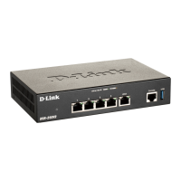
Device Status LEDs and Ethernet Port LEDs
The device LEDs show information about current
device status. When the device power up, the
POWER/STATUS LED will show solid orange
during power on process. Startup takes one minute
approximately to complete, the LED will change
to solid green. If you want to turn the device off
and on again, we recommend you wait a few
seconds between shutting it down and powering it
back. The Ethernet LEDs show the status of each
Ethernet port. Table 2 lists the name, color, status
and description of each device LED.
Figure 2. Ethernet RJ-45 Port LEDs
TX/RX
Status
Link
Speed
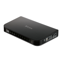
Front Panel - DSR-500/1000
Product Overview
Note: DSR-500 supports one USB port only.
Figure 1. DSR-500/1000 Front Panel
EA C DB
 Loading...