2 D-Link Services Router
ENGLISH
LED
Indicators
Color Status Description
Power /
Status
Orange/
Green
Solid
Orange
Device during power-on
process
Solid Green Completion of power on
Blinking
Orange
Device is crashed and
under recovery mode
Blinking
Green
The system is defective,
such rmware upgrades
fail.
Light Off The device is power-off
USB Green Solid Green The link is good
Blinking
Green
There is activity on
this port
Light Off No link
TX/RX
Status
Green Light Off No Link.
Solid Green Link present.
Blinking
Green
Port is sending or
receiving data.
LINK
Speed
Green/
Orange
Light Off Port is operating at
10Mbps.
Solid Green Port is operating at
100Mbps
Solid
Orange
Port is operating at
1000Mbps
Installing Equipment
Table 2. Device Status LED Descriptions
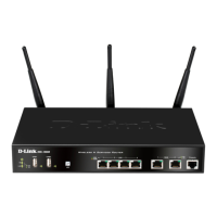
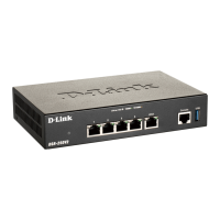
Installing and Connection
This chapter describes how to install a
DSR-500/1000 device in a standard 19-inch
equipment rack and how to connect cables and
power to the device.
Before You Begin
Observe the following precautions to help prevent
shutdowns, equipment failures and injuries:
- Before installation, always check that the power
supply is disconnected.
- Ensure that the room in which you operate the
device has adequate air circulation and that
the room temperature does Not exceed 40
o
C
(104
o
C)
- Allow 1 meter (3 feet) of clear space to the front
and back of the device.
- Do not place the device in an equipment rack
frame that blocks the air vents on the sides of
the chassis. Ensure that enclosed racks have
fans and louvered sides
- Correct these hazardous conditions before
any installation: moist or wet oors, leaks,
ungrounded or frayed power cables, or missing
safety grounds.
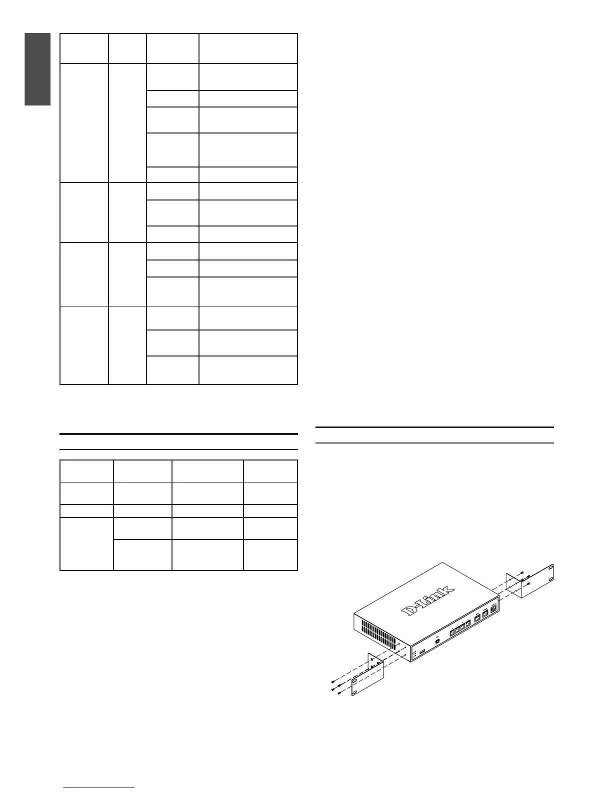
You can mount the DSR-500/1000 device into a
standard 19-inch equipment rack. To install an
appliance into a rack:
1. Attach the mounting brackets to each side of
the chassis as shown in gure 3 and secure
them with the screws provided.
DSR-500/1000 Default Interface Settings
Ethernet
Interface Interface Type IP Address
Web-Based
Management
LAN(1-4) /
WLAN
Static IP 192.168.10.1/24 Enabled
WAN1 DHCP Client 0.0.0.0/0 Disabled
WAN2
(Congurable
port)
DHCP Client
(default)
0.0.0.0/0 Disabled
Static IP (When
it’s congured
as DMZ)
172.17.100.254/24 Disabled
Table 3. Default Interface Settings
Note: D-Link Services Router only allow Web GUI
access from LAN and WLAN interfaces by default
for security reason.
The WAN2 is a congurable port which support
various and advanced scenario applications.
When WAN2 port is congured as DMZ port, the
IP address will be changed to 172.17.100.254.
Figure 3. Attaching Rack Mount Brackets
 Loading...