DXS-1210 Series 10 Gigabit Ethernet Smart Managed Switch Hardware Installation Guide
4
Link/Act
(25GE SFP28 ports)
(DXS-1210-28T only)
Active connection at 25 Gbps through the port
Data transmitted and received through the port
Active connection at 10 Gbps through the port
Data transmitted and received through the port
The behavior of the LEDs during the booting or rebooting process is described in the following table:
DXS-1210-28T
DXS-1210-28S
Blinks green when the switch is powered on.
Then, lights solid green when the system is ready.
Light solid green and amber when the switch is powered on.
Then, alternating between green and amber blink until the system is
ready.
Turns off during the booting or rebooting process.
Turns off during the booting or rebooting process.
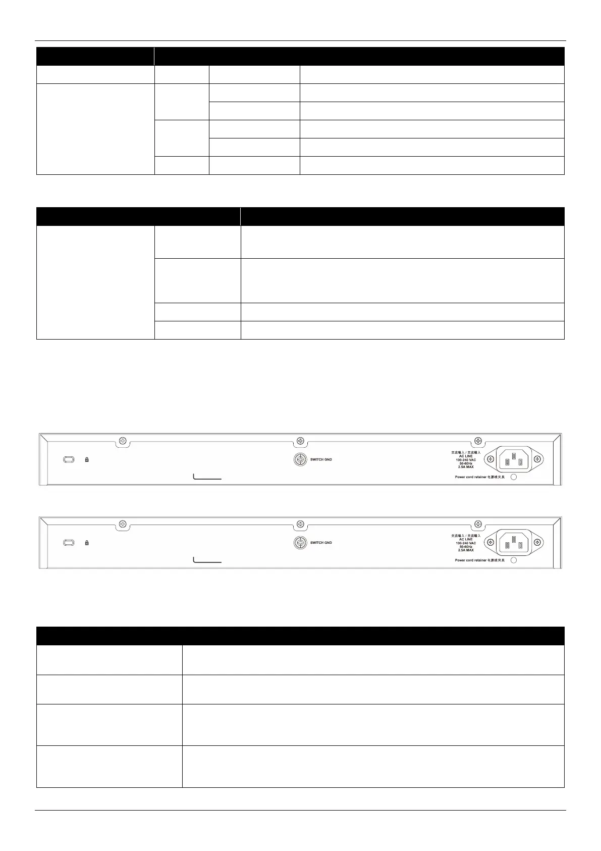
Rear Panel Components
The rear panel features a variety of components and ports.
Figure 2-5 DXS-1210-28T Rear Panel
Figure 2-6 DXS-1210-28S Rear Panel
This following table lists the front panel components on all the switches in the series:
The AC power cord (included in the package) can be plugged into this receptacle
to supply the switch with 100-240 VAC power at 50-60 Hz.
The power cord, retainer hole is used to insert the power cord retainer to secure
the AC power cord.
Use an electrical grounding wire and connect one end of the wire to the switch
GND and the other end of the wire to an electrical grounding point most commonly
found on the Switch mounting rack itself.
The Kensington-compatible security lock can be used to connect the Switch to a
secure immovable device. Insert the lock into the notch and turn the key to secure
the lock. The lock-and-cable apparatus should be purchased separately.
 Loading...