6.2 SurroundView Use Case with Calibration Steps
i. At the main menu, press 5 to select ISS Use Cases.
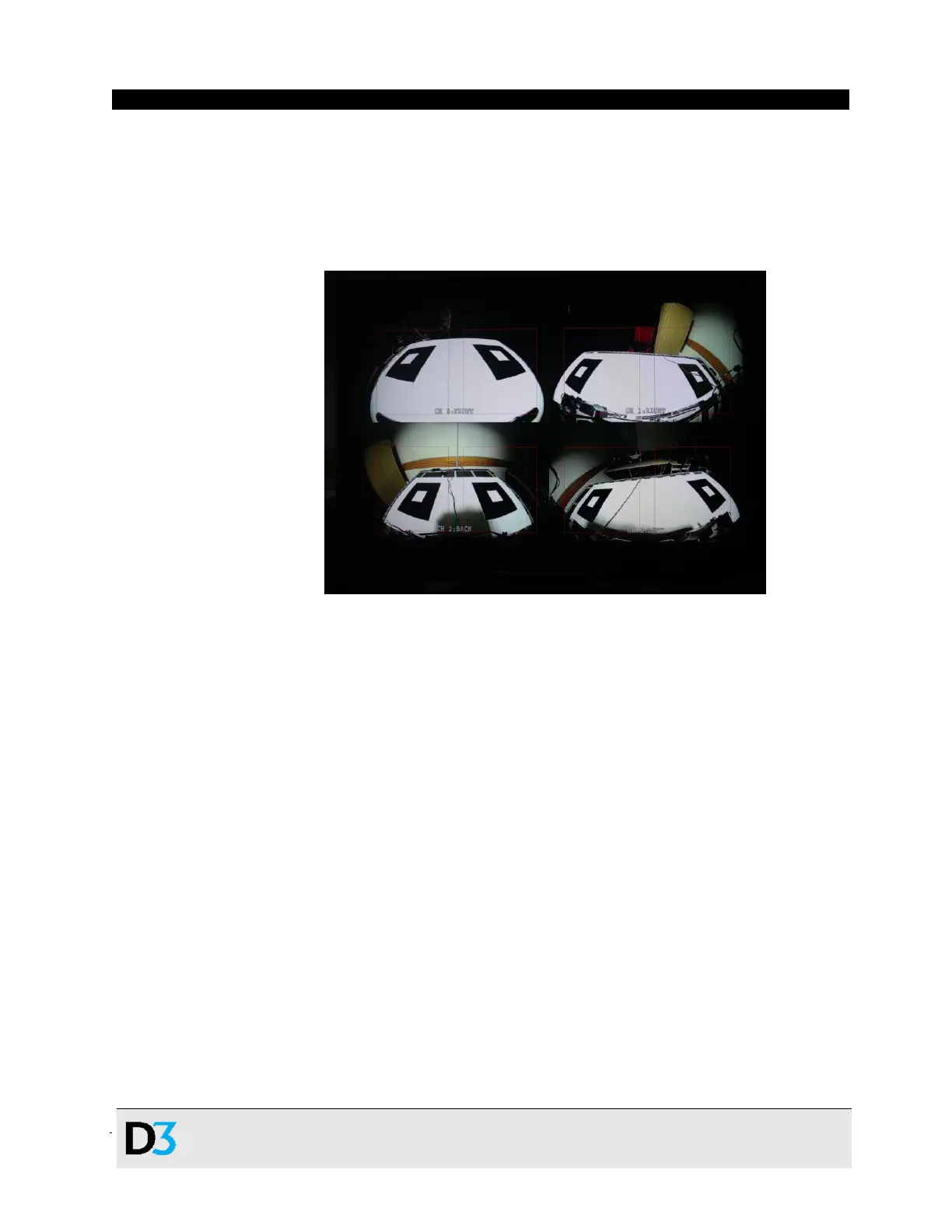
ii. Select option 5 for 3D SRV calibration. Look for an image like Figure 10 (below), on
the display:
Figure 10. Image showing SurroundView calibration
iii. To ensure that the labels on all four cameras match the video feeds – FRONT (VIN4),
RIGHT (VIN3), BACK (VIN2), LEFT (VIN1) – wave your hand in front of each camera.
If the cameras are plugged in in the correct order, these will match; if not, re-plug
them in in the proper order. (See Table 4. Joining the Cameras to the VIN
Connections.)
iv. Position the cameras to center the black squares inside each red rectangle. D3
Engineering recommends pointing the front camera a little higher from the ground
and the rear camera a little lower to accommodate the 3D SurroundView use case’s
field of view.
v. Verify that the black squares are clear in the image and not obstructed. Ensure that
cables run down the centers of the targets away from the black squares.
vi. Select option 1 Auto Calibration from the menu. Over the next several minutes, the
algorithm will draw red squares on the corners of the targets it finds.
vii. Verify that the corners are located correctly, as shown in Figure 12 (below). If
necessary, remove obstructions and press 1 again to retry the calibration.
 Loading...