9
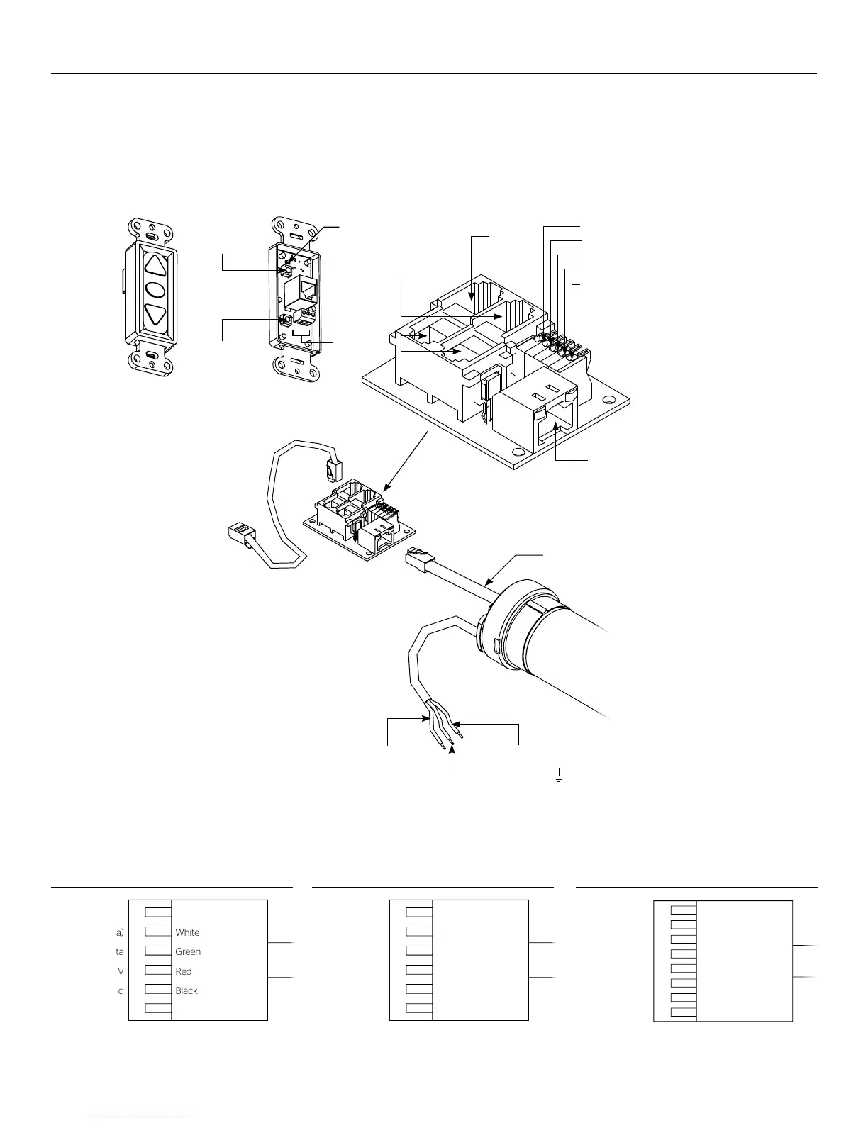
220V Wiring Diagram with Optional Built-In Low Voltage Control
RJ45
Receptacle
RJ22
Output
RJ22
Inputs
Up (Dry Contact)
Down (Dry Contact)
Common (Both)
Bus (Bus)
5V (Bus)
Front of
Wall Switch
Bus
BUS
COM
5V
LED
Up Limit
Tactile Button
Down Limit
Tactile Button
Back of
Wall Switch
RJ22 Pin-Outs (Tab Is Facing Down)
Standard RJ22 can be used in place of RJ14 cable
Bus (RP Data)
+12V
RQ Clock
RQ Data
+5V
Ground
Yellow
Red
Green
Black
White
Blue
RJ45 Pin-Outs (Tab Is Facing Down)
+12V
Manual 2
Ground
Manual 1
RQ Clock
Bus (RP Data)
RQ Data
+5V
Blue
Green
Yellow
Red
Black
Orange
Purple
Brown
220V Wiring Diagram with Operation & Limit Adjustment Wall
Switch
3-conductor 2024 gauge wire can be used in place of the supplied
RJ14 cable to connect the wall switch. Connect the BUS terminals on
the wall switch to the corresponding BUS terminals on the splitter
board.
IMPORTANT NOTE: The wall switch is REQUIRED to make any limit
switch adjustments, EVEN if a third party control system is used.
Therefore, it is advised to wire the switch or provide a 3-conductor
connection that is accessible.
Power Input 220VAC / 50Hz
Green / Yellow (Ground)
Blue
(Hot)
Brown
(Common)
Power
Wire
Data
Cable
RJ45 Jack
RJ22 Jack
(Connection to
Wall Switch)
RJ22
Jack
RJ14 Pin-Outs (Tab Is Facing Down)
Supplied RJ14 cable
Bus (RP Data)
RQ Data
+5V
Ground
White
Green
Red
Black