ENGLISH
45
RISK OF FROST: pay attention to the installation site of ACTIVE DRIVER! Take the following
precautions:
If the ACTIVE DRIVER is operative it is absolutely necessary to protect it adequately against frost and to
leave it constantly powered. If it is disconnected from the power supply, the anti-frost function is no longer
active!
If the ACTIVE DRIVER is not operative it is necessary to turn off the power supply, disconnect the
appliance from the pipe and completely empty out all water left inside.
It is not sufficient just to remove pressure from the pipe, because some water is always left inside.
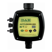
1.8 GENERAL CHARACTERISTICS
ACTIVE DRIVER is an innovative system for pumps, which maintains constant pressure on variation of
flow rates, regulating pump speed accordingly.
The ACTIVE DRIVER comprises an inverter, a pressure sensor and a flow sensor.
The ACTIVE DRIVER is equipped with 3 inputs and 2 outputs.
Figure 5 shows the connection diagram of the outputs, terminal J14.
Figure 6 shows the connection diagram for 2 ACTIVE DRIVER units, for the exchange and dialogue
functions.
Figure 7shows the connection diagram of the utility input terminals J22.
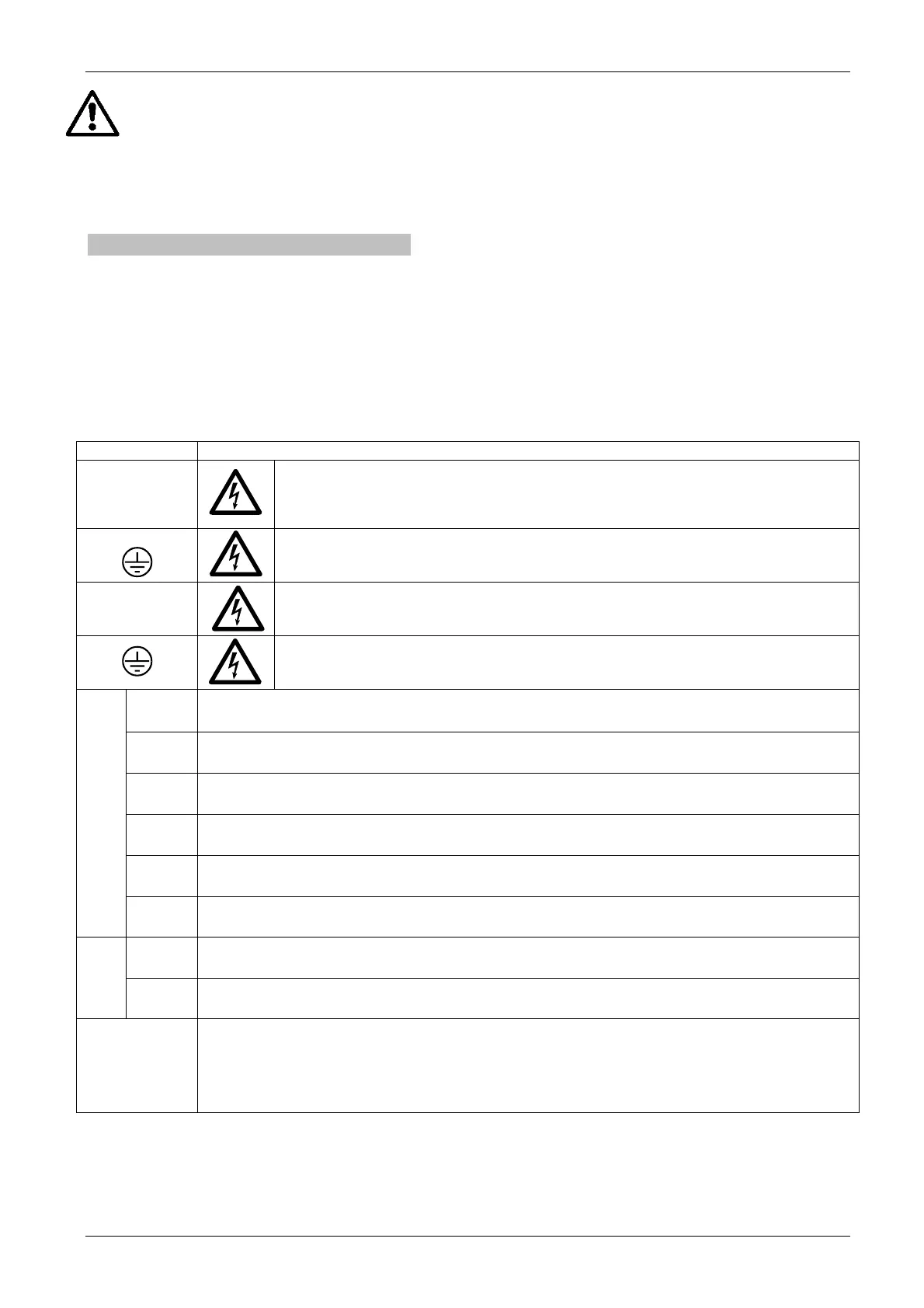
Ref. FUNCTION
L – N
SINGLE-PHASE
R – S – T
THREE-PHASE
Power supply line connection terminals.
Connection terminal to power supply earthing.
U - V – W
THREE-PHASE
Three-phase electric pump connection terminals.
Electric pump earth system connection terminal.
1
Power supply terminal: + 12V DC – 50 mA.
2=IN 3
Connection terminal of input i3 for general enabling command.
3=IN 2
Connection terminal of input i2 for selecting set point 1.
4
Common connection terminal I3 – I2
6=IN 1
Connection terminals of input i1 for protection against dry running.
J22
7
Connection terminal: 0V DC (GND).
o1
Remote alarm connection terminal.
250 Vac – 6 A max. resistive load – 3 A max. inductive load
J14
o2
Pump operating connection terminal.
250 Vac – 6 A max. resistive load – 3 A max. inductive load
J9
Connection terminals for interconnection and exchange and for connection with the expansion
control unit, see Figure 6.
CAUTION: In the case of interconnection cables exceeding the length of 1 m, use a twisted
cable (with twisted pair), one pair for pins 1 and 3 and another pair for pin 2.
CAUTION: Strictly observe the connection sequence between the two appliances! (see fig.2)
 Loading...