ENGLISH
47
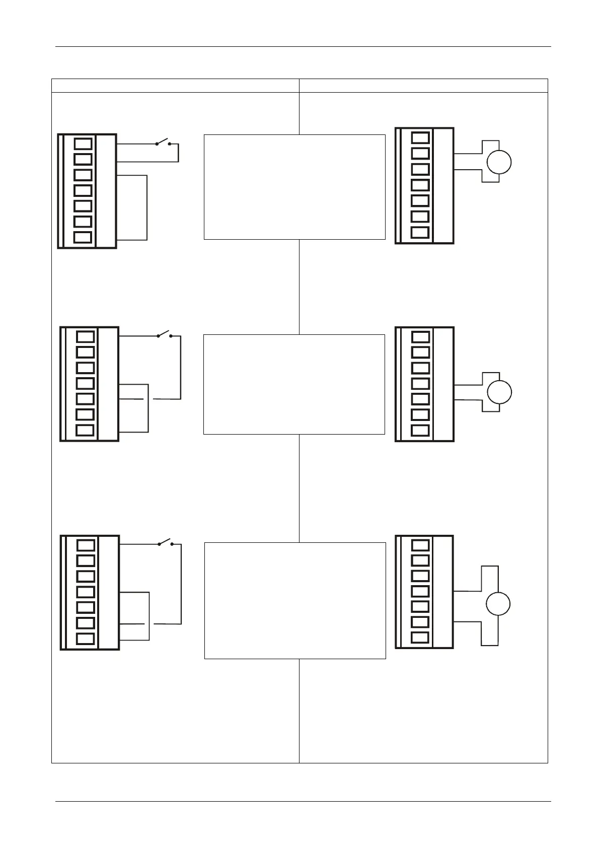
Figure 7 - Example of possible uses of the utility inputs -
Control with voltage-free contact Control with external voltage
Figure 7: Inputs
Example: Use of IN 1
When IN 1 is activated the pump is
blocked and the signal “F1” is
displayed
ex. IN 1 could be connected to a
float
Example: Use of IN 2
When IN 2 is activated the regulating
pressure becomes “P1”
(switch over active setpoint:
SP or P1)
Example: Use of IN 3
When IN 3 is activated the electric
pump is blocked and the signal “F3”
is displayed
ex. IN 3 could be connected to a
safety pressure switch with
manual reset
Jumper
Jumper
1
2
3
4
5
6
7
1
2
3
4
5
6
7
1
2
3
4
5
6
7
AC/DC
1
2
3
4
5
6
7
AC/DC
1
2
3
4
5
6
7
AC/DC
J22
J22
Jumper
J22
J22
J22
Supplied with direct
voltage
(Max. 36V) or
alternate voltage
(Max. 24Vrms)
Supplied with direct
voltage
(Max. 36V) or
alternate voltage
(Max. 24Vrms)
Supplied with direct
voltage
(Max. 36V) or
alternate voltage
(Max. 24Vrms)
Voltage-free contact
Voltage-free contact
Voltage-free contact
1
2
3
4
5
6
7
 Loading...