ENGLISH
32
9. ES 0,75 T-ES 1 T-ES 1,5 T-ES 3 T-ES 4 T-ES 7,5 T-ES 10 T-ES 12,5 T-ES 15 T
ES 20 T-ES 25 T-ES 30 T-ES 40 T-ES 7,5 T SD-ES 10 T SD-ES 12,5 T SD-ES 15 T SD
ES 20 T SD-ES 25 T SD-ES 30 T SD-ES 40 T SD
9.1
Technical data
rated input voltage:
400 V +/- 10%
phases:
3
frequency:
50-60 Hz
ES 0,75 T ES 1 T ES 1,5 T
ES 3 T ES 4 T ES 7,5 T
max. rated output power (KW):
0,89 1,38 2,2 3,5
5,5 7,7
max. rated using current (A):
1,6 2,5 4 6,3
10 14
ES 10 T ES 12,5 T ES 15 T ES 20 T ES 25 T ES 30 T
max. rated output power (KW):
9,9 13,8 13,8 17,7 22,1 34,8
max. rated using current (A):
18 25 25 32
40 63
ES 40 T
max. rated output power (KW):
44,3
max. rated using current (A):
80
ES 7,5 T SD ES 10 T SD
ES 12,5 T SD
ES 15 T SD
ES 20 T SD ES 25 T SD
max. rated output power (KW):
9,9 9,9 13,8 13,8
17,7 22,1
max. rated using current (A):
18 18 25 25
32 40
ES 30 T SD
ES 40 T SD
max. rated output power (KW):
34,8 44,3
max. rated using current (A):
63 80
field of use environment temperature:
-10°C +40°C
storage environment temp. limit:
-25°C +55°C
relative humidity (without condensation):
50% at 40°C MAX (90% at 20°C )
max. altitude:
3000 m (a.s.l.)
degree of protection:
IP55
panel construction:
in accordance with EN 60204-1 and EN 60439-1
9.2 Characteristics and interpretation of the wiring diagram references.
The panel is self-protected and protects the electropump against overloads, short circuits and overtemperatures, with manual
reset. It comes complete with terminals for connecting the motor, the pressure switches and the control electro-probes.
Complete with terminals (without potential) for remote feeding of an acoustic or luminous alarm. Provided with a button for manual
or automatic operation of the electropump, timer for regulating the pause time against dry operation, microswitch for selecting
function with 1 or 2 probes, microswitch for selecting protection against excessive starts. Setting for draining or filling operation.
The internal transformer is supplied complete with a self-resetting protection against overloads or
short circuits, which manually cuts out the supply voltage for 3 minutes.
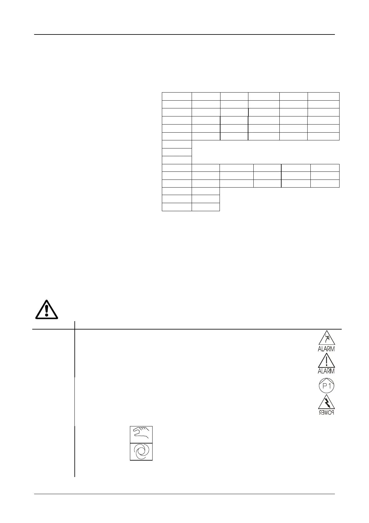
Ref. Function (see references on the wiring diagrams)
HL4
Red warning light indicating intervention of the overload protection of the electropump
HL2
Red warning light indicating protection against dry running or excessive starts.
HL3
Green warning light indicating that the electropump is being fed
HL1
White warning light indicating correct operation of the auxiliary circuits
SA1
Selector for MANUAL - 0 – AUTOMATIC operation of each electropump where:
MANUAL
= electropump P1 is manually controlled by the operator as long as the
control is maintained
AUTOMATI C
= electropump P1 is controlled directly by the pressure switches,
thermostats or other devices .
QM1
Automatic magnetothermal switch, for protection of the P1 motor supply line against overloads and short
circuits, with manual reset.
 Loading...