ENGLISH
34
9.3.7
The system must be correctly and safely earthed as required by the regulations
in force.
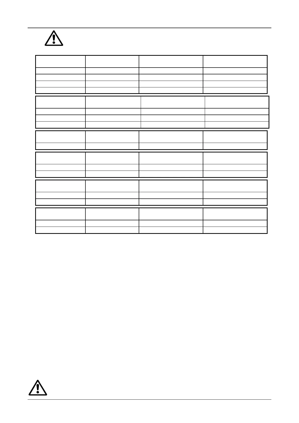
9.3.8 Depending on the type of installation, limit the maximum length of the power cable as follows:
Panel model Max. line length ( m )
( section 1.5 mm
2
)
Max. line length ( m )
( section 2.5 mm
2
)
Max. line length ( m )
( section 4 mm
2
)
ES 0,75 T
200 340 550
ES 1 T
130 220 350
ES 1,5 T
85 140 220
ES 3 T
50 90 140
Panel model Max. line length ( m )
( section 2.5 mm
2
)
Max. line length ( m )
( section 4 mm
2
)
Max. line length ( m )
( section 6 mm
2
)
ES 4 T
55 90 130
ES 7,5 T
40 65 95
ES 7,5 T SD
30 50 75
Panel model Max. line length ( m )
( section 4 mm
2
)
Max. line length ( m )
( section 6 mm
2
)
Max. line length ( m )
( section 10 mm
2
)
ES 10 T/ES 10 T SD
50 75 125
Panel model Max. line length ( m )
( section 6 mm
2
)
Max. line length ( m )
( section 10 mm
2
)
Max. line length ( m )
( section 16 mm
2
)
ES 12,5 T/ES 12,5 T SD
50 90 140
ES 15 T/ES 15 T SD
50 90 140
Panel model Max. line length ( m )
( section 10 mm
2
)
Max. line length ( m )
( section 16 mm
2
)
Max. line length ( m )
( section 25 mm
2
)
ES 20 T/ES 20 T SD
70 110 170
ES 25 T/ES 25 T SD
55 90 140
Panel model Max. line length ( m )
( section 16 mm
2
)
Max. line length ( m )
( section 25 mm
2
)
Max. line length ( m )
( section 35 mm
2
)
ES 30 T/ES 30 T SD
55 90 120
ES 40 T/ES 40 T SD
45 70 95
9.3.9
Instrumental checks to be carried out by the installer:
a) continuity of the protection leads and of the main and supplementary equipotential circuits;
b) insulation resistance of the electric system;
c) test efficiency of the differential protection;
d) test the applied voltage;
e) test operation as indicated in point 9.5
9.4 Connection of the electro-probes
Use a lead with a section of 1.5 mm
2
.
Insert the rubber cap or the cable clamp in the electro-probe connecting lead.
Connect the lead to the electrode.
Electro-probes with a rubber ring: insert the electro-probe in the rubber cap previously inserted until the two lead
retaining screws are covered.
Electro-probes with cable clamp: screw the cable clamp onto the electro-probe, ensuring that it is firmly secured.
Make the connection to the panel by means of the terminals I, L and M as indicated on page 26
9.5 Starting the system
1. Connect the electropump to the terminals U-V-W
2. Ensure that the external control B is in OFF position (command excluded).
ATTENTION: if the remote control for connection to the terminals B is not used, the electropump is started
by turning on the main switch..
3. After having set the functions of ref., SP1-SP2-D1, close the door.
4. Supply power to the panel by turning on the main switch on the distribution panel.
5. Turn the selector ref. SA1 to position MAN. The electropump is fed as long as it remains pressed.
6. Turn the selector ref. SA1 to position AUT. Activate the remote control function B and check that the warning light
ref. HL3 comes on to show that the electropump is being fed.
Avoid starting the system, turning the isolating switch (ref. QS1) with the switch ref.
QM1 in position I.
 Loading...