ENGLISH
33
Set on QM1 the current indicated on the motor data plate.
QS1
Supply line insulating switch with door locking handle which may be padlocked.
D1
Manual regulation of the minutes scale for setting the pause time from 3 to 12 minutes after intervention of
the protection against dry operation (on the M2S module).
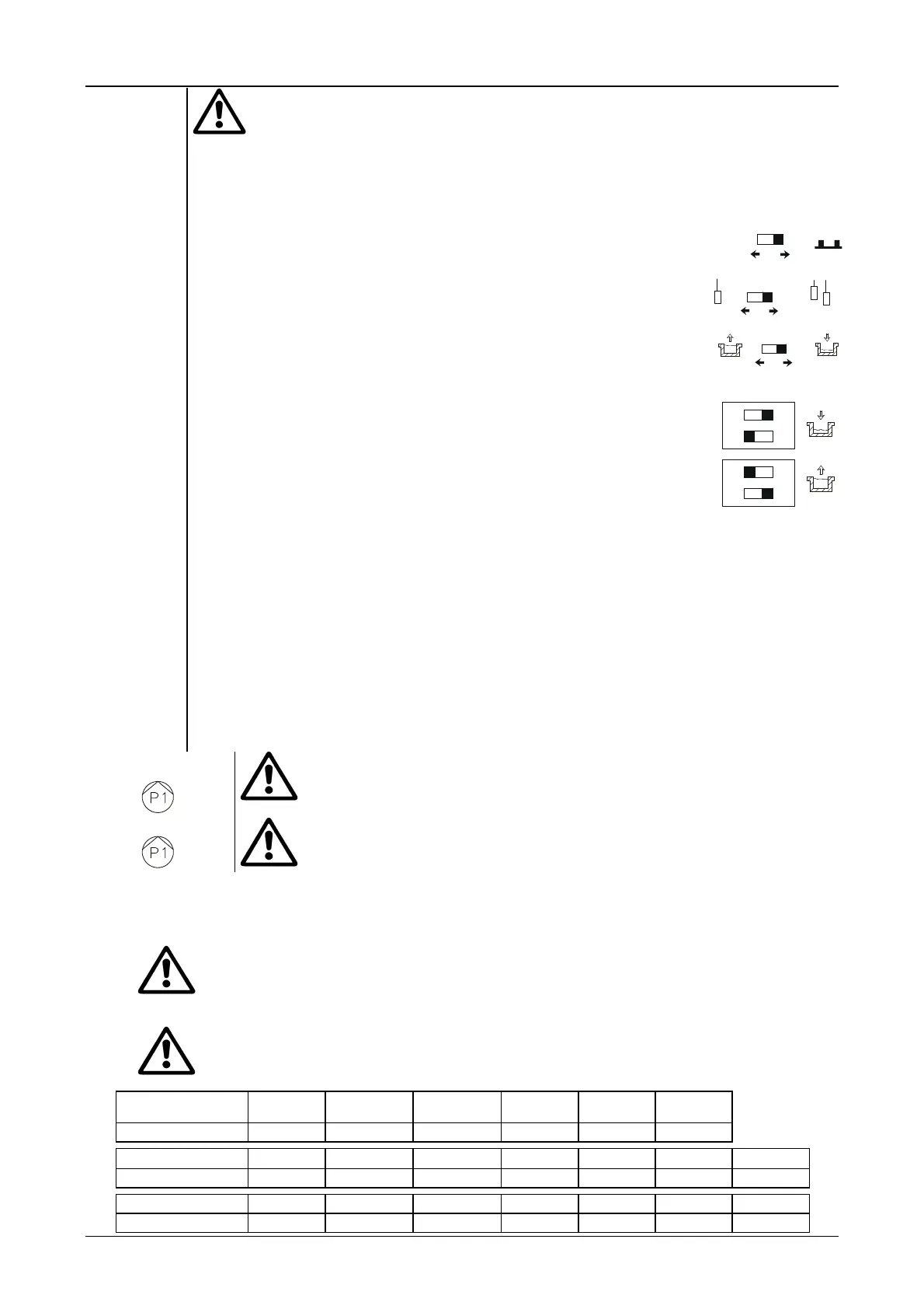
SP1
microswitch (on the M2S module) for manual setting of the following functions:
Switch “1”: forced stopping of the electropump if an excessive number of
starts is requested. MAX one start per minute.
Switch “2”: setting of system operation according to the number of electro-
probes that are to be used.
Switch “3”: setting for draining or filling operation (possible only with the
support of two probes).
OFF
1
60
L
L
M
2
3
SP2
microswitch (on the M2S module) for manual setting of the electro-probes for draining or filling.
Switch “1”: when this switch is turned ON the electro-probes are set for
draining operation. ATTENTION: the switch “2” must NOT be ON.
Switch “2”: when this switch is turned ON the electro-probes are set for
filling operation. ATTENTION: the switch “1” must NOT be ON.
2
1
ON
1
2
ON
Q
31 - 32
Connection terminals for the remote alarm for indicating intervention of the protection against dry
operation and excessive starts.
Contact characteristics: without potential, NO (normally open); 5 Amp; 250V.
B
3 - 4
Connection terminals 24 a.c. for the pressure switch, water level control float or other remote control to be
connected, removing the jumper. Maximum resistance allowed for the control circuits 5 K.
I
18
Connection terminal 24V a.c. for the common electro-probe to be used in systems where the water is not in
direct contact with the earth system (Maximum resistance of electro-probe less than or equal to 80 Kohm).
L
19
Connection terminals 24V a.c. for the electro-probe that controls the maximum level or dry operation
depending on the setting as in ref. SP1 (Maximum resistance of electro-probe less than or equal to 80
Kohm).
M
20
Connection terminal 24V a.c. for the maximum level control electro-probe. (Maximum resistance of
electro-probe less than or equal to 80 Kohm).
U-V-W
Electropump connection cables for direct start.
Scrupulously respect the required correspondence.
U1-V1-W1 U2-V2-W2
Electropump connection cables for star-delta start.
Scrupulously respect the required correspondence.
9.3 Electrical connections
9.3.1 Before connecting the power cables to terminals L1 - L2 - L3 of the insulating switch, ensure that the main switch on the
power distribution panel is in OFF position (O), and that no one can switch on the power accidentally.
9.3.2 Scrupulously observe all the regulations in force concerning safety and accident prevention.
9.3.3
Ensure that all the terminals are fully tightened, paying particular attention to the earth terminal.
9.3.4 Connect the cables to the terminal board as indicated in the wiring diagrams given in the enclosed booklet.
9.3.5 Check that all the connecting cables are in excellent condition, with the external sheathing unbroken.
9.3.6
Check that the differential switch that protects the system is of the right size.
Provide automatic protection of the supply line against short circuits by means of
ACR fuses type “gG” according to the following table:
PANEL MODEL
ES 0,75 T ES 1 T ES 1,5 T
ES 3 T ES 4 T
ES 7,5 T
ES 7,5 T SD
FUSES 6A 10A 16A 20A 25A 32A
PANEL MODEL ES 10 T ES 12,5 T ES 15 T ES 20 T ES 25 T ES 30 T ES 40 T
FUSES 40A 50A 63A 80A 100A 125A 160A
PANEL MODEL
ES 10 T SD ES 12,5 T SD ES 15 T SD ES 20 T SD ES 25 T SD ES 30 T SD ES 40 T SD
FUSES 40A 50A 63A 80A 100A 125A 160A
 Loading...