Installation 6
Aim the lens to the ideal angle, and then adjust the focus and zoom until you get clear Step 5
image, see Figure 3-2. Fasten the fixing ring⑤ afterwards.
Model A adjustment
Figure 3-2
Installing Model B (1) and Model B (2) 3.2
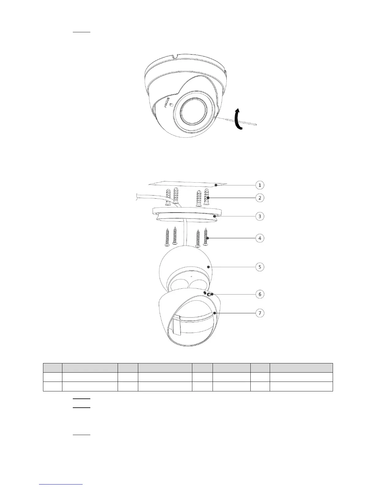
Model B (1) and Model B (2) installation Figure 3-3
Table 3-2 Installation item list
Loosen the locking screw⑥ with the supplied wrench and take the pedestal③ off. Step 1
Confirm the position of screw holes (and the cable outlet hole if it needs to go through Step 2
the mounting surface①) and drill them on the mounting surface①, and then insert the
expansion bolts② in the screw holes.
Align the screw holes on the pedestal③ to those on the mounting surface①, and then Step 3
pull the cable out through mounting surface or the side cable tray. Attach the pedestal
③ to the mounting surface① with the self-tapping screws④.
 Loading...