Installation 12
Put the fixing ring⑦ and the enclosure⑥ back on, and then connect the device⑤ to Step 5
power source and the XVR device, and the live view screen is displayed.
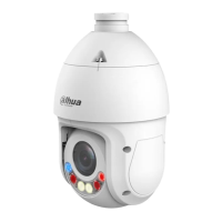
Aim the lens to the ideal angle, see Figure 3-12.
Step 6
Model F adjustment Figure 3-12
Installing Model G (1) and Model G (2) 3.7
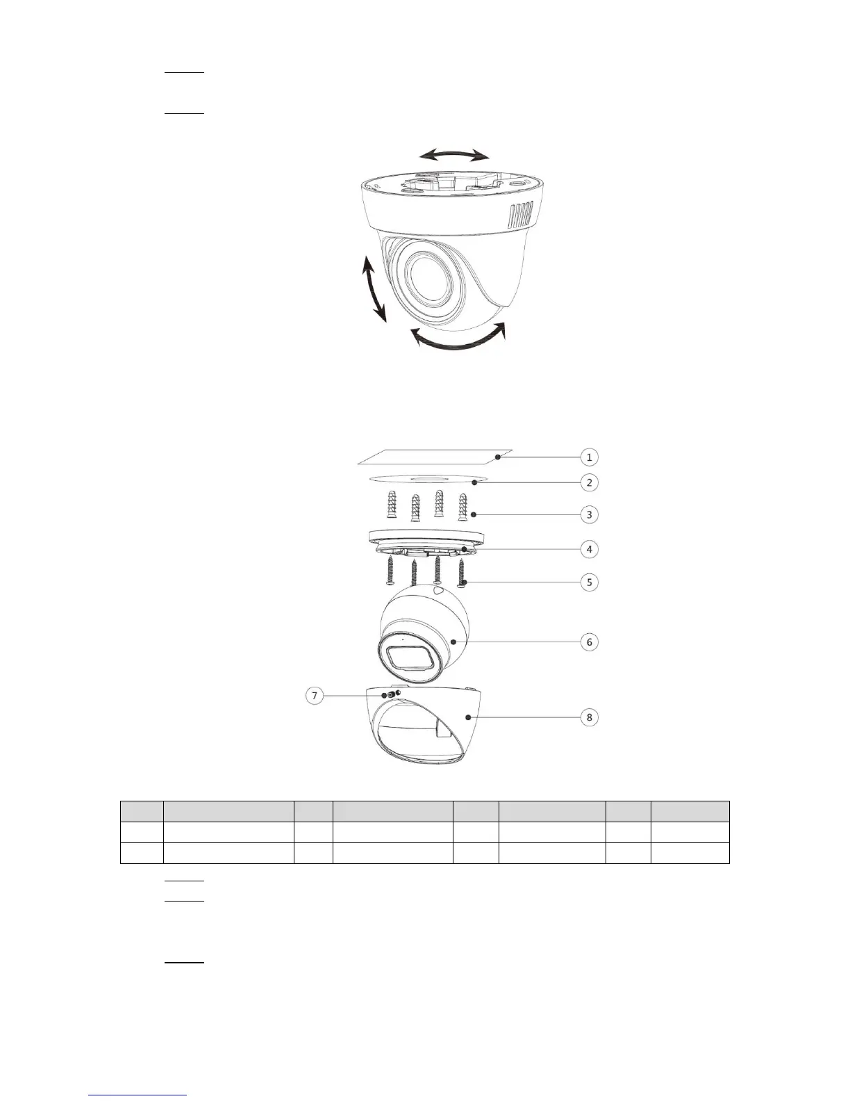
Model G (1) and Model G (2) installation Figure 3-13
Table 3-7 Installation item list
Loosen the locking screw⑦ with the supplied wrench and take the pedestal④ off. Step 1
Confirm the position of screw holes (and the cable outlet hole if it needs to go through Step 2
the mounting surface①) as the positioning map② shows and drill them on the
mounting surface①, and then insert the expansion bolts③ in the screw holes.
Align the screw holes on the pedestal④ to those on the mounting surface①, and then Step 3
pull the cable out through mounting surface or the side cable tray. Attach the pedestal
④ to the mounting surface① with the self-tapping screws⑤.
 Loading...