3.1 Screen Design Basics
3-1
3.1 Screen Design Basics
3.1.1 Number of screens and layout of operation switches
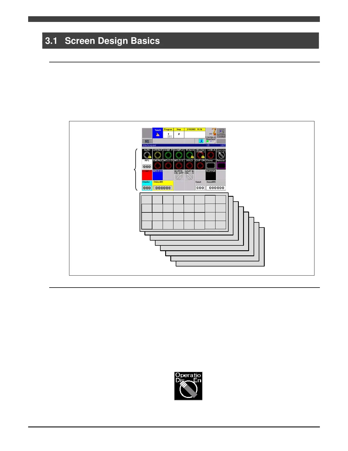
Up to 8 screens each with a maximum of 31 keys can be designed. This means that a total of 248 keys (31 keys per
screen x 8 screens) can be laid out.
There is no need to use all 8 screens. Define only those screens required to suit the desired operation method.
When opening the screens, the ones on which no soft keys have been defined will not be displayed.
The operation switches and other soft keys laid out on the screens are each identified by a number that consists of
the screen page number and position number as shown in the figure below, and the screens are designed by
specifying these numbers.
Interface
panel
1
1B
1C
1D 1E 1F
1G 1H
2A
2B 2C 2D 2E 2F
2G
2H
3A 3B
3C
3D 3E 3F
3G 3H
4A
4B 4C 4D 4E 4F
4G 4H
P1
P2
P3
P4
P5
P6
P7
P8
Example:
Key in upper left-hand
corner of first screen
(P1-1A)
Fig. 3.1.1 Key layout on interface panel screen
3.1.2 Reserved switch in upper right-hand corner
The position in the upper right-hand corner (1H) of each page is always reserved by the system for a switch that
executes a specific application, and it cannot be changed.
This is the selector switch that enables or disables interface panel operations. This switch functions when it is
pressed together with the [ENABLE] key or individually by itself, according to the setting of “Common switch
operation method” item in the “Interface panel condition setting” menu. If the “Common switch operation method”
item is set to “Standard”, the switch will function individually by itself. If the item is set to “Enable simultaneous”, the
switch will function by pressing it together with the [ENABLE] key. Furthermore, according to the setting of “Common
switch ON direction” item in the “Interface panel condition setting” menu, whether the switch is inhibited to operate in
the left or the right direction can be set as well.
Since the interface panel uses a touch panel, just touching the touch panel will execute the function. Use this switch
to lock the touch panel so that the actuator will not perform an unintended operation due to mishandling or the
interface panel will not function when the surface of the LCD display is cleaned. However, panels that have been
registered by switching the “operation inhibit” item while in detailed setting to “Disable” are able to surely operate
regardless of the status of this reserved switch.
Fig. 3.1.2 Selector switch for enabling/disabling operations always
provided at upper right-hand corner of each page

 Loading...