7 Installation
Installer reference guide
27
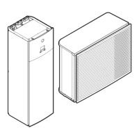
ERLQ004~008CAV3 + EHBH/X04+08CA
Daikin Altherma - Low Temperature Split
4P313774-1C – 2012.11
Item Description Wires Maximum
running
current
Outdoor unit and indoor unit power supply
1 Power supply for
outdoor unit
2+GND or
3+GND
(a)
2 Power supply and
interconnection cable to
indoor unit
3
(c)
3 Power supply for
backup heater
See table below. —
4 Preferential kWh rate
power supply (voltage
free contact)
2
(e)
5 Normal kWh rate power
supply
2 6.3 A
User interface
6 User interface 2
(f)
Optional equipment
7 3‑way valve 3 100 mA
(b)
8 Power supply for
booster heater and
thermal protection
(from indoor unit)
4+GND
(c)
9 Power supply for
booster heater (to
indoor unit)
2+GND 13 A
10 Domestic hot water
tank thermistor
2
(d)
11 Power supply for
bottom plate heater
2
(b)
12 Room thermostat 3 or 4 100 mA
(b)
13 Outdoor ambient
temperature sensor
2
(b)
14 Indoor ambient
temperature sensor
2
(b)
15 Heat pump convector 4 100 mA
(b)
Field supplied components
16 Shut-off valve 2 100 mA
(b)
17 Electricity meter 2 (per meter)
(b)
18 Domestic hot water
pump
2
(b)
19 Alarm output 2
(b)
20 Changeover to external
heat source control
2
(b)
21 Space cool/heat
operation control
2
(b)
22 Power consumption
digital inputs
2 (per input
signal)
(b)
(a) Refer to name plate on outdoor unit.
(b) Minimum cable section 0.75 mm².
(c) Cable section 2.5 mm².
(d) The thermistor and connection wire (12 m) are delivered with the
domestic hot water tank.
(e) Cable section 0.75 mm² till 1.25 mm²; maximum length: 50 m.
Voltage-free contact shall ensure the minimum applicable load of
15 V DC, 10 mA.
(f) Cable section 0.75 mm² till 1.25 mm²; maximum length: 500 m.
Applicable for both single user interface and dual use interface
connection.
NOTICE
More technical specifications of the different connections
are indicated on:
▪ Wiring diagram in the switch box of the unit
▪ "15.6 Wiring diagram" on page 84
Backup heater
type
Power supply Required number of
conductors
*3V 1x 230 V 2+GND
*9W 1x 230 V 2+GND + 2 bridges
3x 230 V 3+GND + 1 bridge
3x 400 V 4+GND
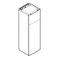
7 Installation
7.1 Opening the units
7.1.1 To open the outdoor unit
1 Remove 1 screw from the service cover.

 Loading...