15 Technical data
Installer reference guide
79
ERLQ004~008CAV3 + EHBH/X04+08CA
Daikin Altherma - Low Temperature Split
4P313774-1C – 2012.11
15.3 Components
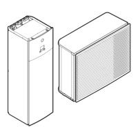
15.3.1 Components: Outdoor unit
a Switch box main PCB (inverter and control PCB)
b Terminal communication and power supply
c Service PCB
d 4-way valve
e Electronic expansion valve (main)
f Accumulator
g Compressor
h Liquid stop valve
i Gas stop valve
j Service port
k Fan motor
l Heat exchanger
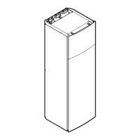
15.3.2 Components: Switch box (outdoor unit)
a Switch box
Contains the main electronic and electrical parts of the indoor
unit.
b User interface (accessory)
c Manometer
Allows readout of the water pressure in the water circuit.
d Air purge valve
Remaining air in the water circuit will be automatically removed
via the air purge valve.
e Expansion vessel (10 l)
f Flow sensor
Gives feedback to the interface about the actual flow. Based on
this information (and other), the interface adjusts the pump
speed.
g Heat exchanger
h Water pump
Circulates the water in the water circuit.
i Water filter
Removes dirt from the water to prevent damage to the pump or
blockage of the heat exchanger.
j Pressure relief valve
Prevents excessive water pressure in the water circuit by
opening at 3 bar.
k Refrigerant gas connection R410A
l Refrigerant liquid connection R410A
m Water inlet connection
n Drain and fill valves
o Shut-off valves (accessory)
Allows isolation of the indoor unit water circuit side from the
residential water circuit side.
p Water outlet connection
q Thermistors
Determines the water and refrigerant temperature at various
points in the circuit.
r Backup heater thermal fuse
The fuse is blown when the temperature becomes higher than
the backup heater thermal protector temperature.
s Backup heater thermal protector
The protector activates when the temperature of the backup
heater becomes too high.

 Loading...