15 Technical data
Installer reference guide
80
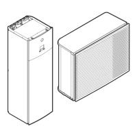
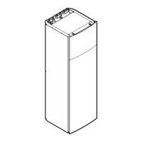
ERLQ004~008CAV3 + EHBH/X04+08CA
Daikin Altherma - Low Temperature Split
4P313774-1C – 2012.11
t Backup heater
Provides additional heating in case of cold outdoor
temperatures. Also serves as backup in case of malfunctioning
of the outdoor unit.
u Air valve
15.3.4 Components: Switch box (indoor unit)
a Pump PCB A7P (Inverter PCB)
b Backup heater thermal protector Q1L
c Transformer TR1
d Terminals for backup heater X6M/X7M (*9W models only)
e Backup heater contactors K1M, K2M and K5M
f Booster heater contactor K3M
g Connectors X6YA/X6YB/X6Y
h Backup heater circuit breaker F1B
i Booster heater circuit breaker F2B. (Only for installations with
domestic hot water tank)
j Terminal block X2M (high voltage)
k Terminal block X3M. (Only for installations with domestic hot
water tank)
l Terminal block X1M (to outdoor unit)
m Cable tie mountings
n Digital I/O PCB A4P (only for installations with solar kit or digital
I/O PCB kit)
o Demand PCB for power limitation
p Terminal block X5M (low voltage)
q Socket X13A, receives the K3M connector. (Only for
installations with domestic hot water tank)
r Main PCB A1P
s Socket X9A, receives the thermistor connector. (Only for
installations with domestic hot water tank)
t PCB fuse FU1

 Loading...