15 Technical data
Installer reference guide
81
ERLQ004~008CAV3 + EHBH/X04+08CA
Daikin Altherma - Low Temperature Split
4P313774-1C – 2012.11
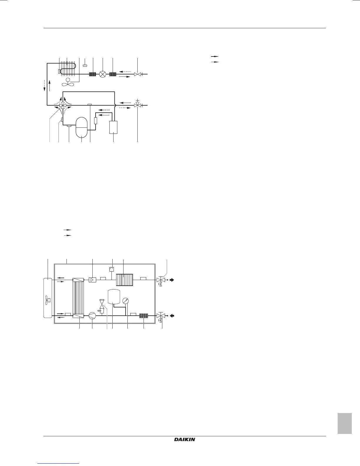
15.4 Functional diagrams
15.4.1 Functional diagram: Outdoor unit
M
a c b d e f e g
n l k i h
m j
a Heat exchanger thermistor
b Fan motor
c Heat exchanger
d Air thermistor
e Filter
f Electronic expansion valve
g Liquid stop valve
h Gas stop valve with service port
i Accumulator
j Pressure sensor
k Compressor
l Discharge thermistor
m High pressure switch
n 4-way valve (ON=heating)
Heating
Cooling
15.4.2 Functional diagram: Indoor unit
R4T
R3T
R2TR1T
m h c klf
ei
a b jg
d
a Outdoor unit
b Indoor unit
c Expansion vessel
d Manometer
e Air purge valve
f Pressure relief valve
g Backup heater
h Pump
i Flow sensor
j Shut-off valve water outlet with drain and fill valve
(field installation)
k Shut-off valve water inlet with drain valve (field
installation)
l Filter
m Heat exchanger
R1T Outlet water heat exchanger thermistor
R2T Outlet water backup heater thermistor
R3T Refrigerant liquid side thermistor
R4T Inlet water thermistor
Heating
Cooling

 Loading...