Installation and operation manual
78
EKEQMCBV3
Option kit for combination of Daikin condensing units
with field supplied air handling units
4PW52447-1
INSTALLATION OF THE ELECTRICAL CONTROL BOX
(See figure 3)
Mechanical installation
1 Fix the control box with its hanger brackets to the mounting
surface.
Use 4 screws (for holes of Ø6 mm).
2 Open the lid of the control box.
3 For electrical wiring: refer to paragraph "Electric wiring work" on
page 78.
4 Install the screw nuts.
5 Close the unnecessary openings with stoppers (closing cups).
6 Close the lid securely after installation to ensure that the control
box is watertight.
ELECTRIC WIRING WORK
■ All field supplied parts and materials and electric works must be
conform to local codes.
■ Use copper wire only.
■ All wiring must be performed by an authorized electrician.
■ A main switch or other means for disconnection, having a
contact separation in all poles, must be incorporated in the fixed
wiring in accordance with relevant local and national legislation.
■ Refer to the installation manual attached to the outdoor unit for
the size of power supply electric wire connected to the outdoor
unit, the capacity of the circuit breaker and switch, wiring and
wiring instructions.
■ Attach the earth leakage circuit breaker and fuse to the power
supply line.
Connection of the wires inside the control box
1 For connection to outdoor unit and to controller (field supply):
Pull the wires inside through the screw nut and close the nut
firmly in order to ensure a good pull relieve and water protection.
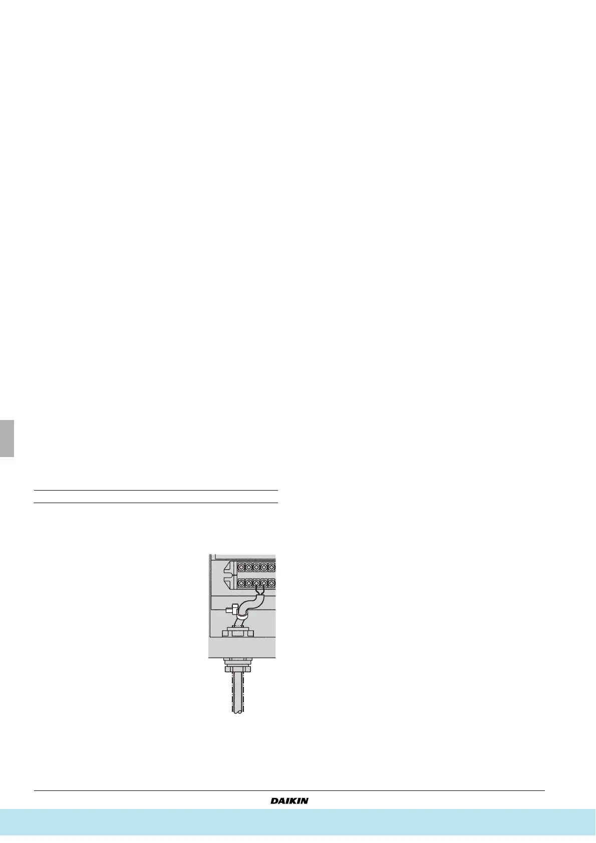
2 The cables require an additional pull-
relief. Strap the cable with the installed tie
wrap.
Precautions
■ Thermistor cable and remote controller wire should be located at
least 50 mm away from power supply wires and from wires to
the controller. Not following this guideline may result in
malfunction due to electrical noise.
■ Use only specified wires, and tightly connect wires to the
terminals. Keep wiring in neat order so that it does not obstruct
other equipment. Incomplete connections could result in
overheating, and in worse case electric shock or fire.
1 Control box
2 Hanger brackets
3 Main PCB
4 Transformer
5 Terminal
6 Optional PCB (KRP4)
Все каталоги и инструкции здесь: http://splitoff.ru/tehn-doc.html