SiBE01-829 Check
Service Diagnosis 57
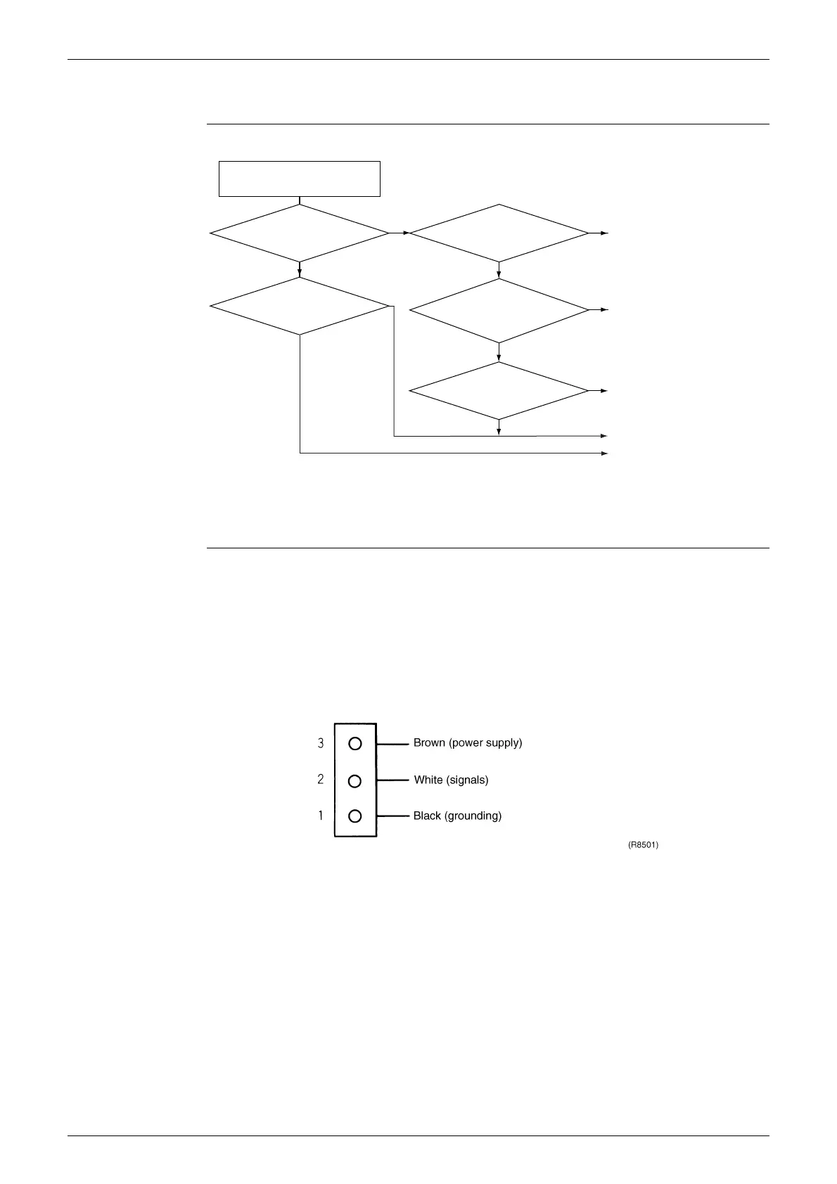
5.3 Outdoor Unit Fan System Check
Check No.09
5.4 Hall IC Check
Check No.16 1. Check the connector connection.
2. With the power ON, operation OFF, and the connector connected, check the following.
∗
Output voltage of about 5 V between pins 1 and 3.
∗
Generation of 3 pulses between pins 2 and 3 when the fan motor is operating.
Failure of (1)
faulty PCB
Replace the PCB.
Failure of (2)
faulty Hall IC
Replace the fan motor.
Both (1) and (2) result
Replace the PCB.
Check the
fan motor lead wire
connector for secure
connection.
Abnormal
YES
NO
YES
Continuity
Are the
resistance at connector
leads ∞? 1. red - black,
2. white - black
Check the fan
capacitor for continuity.
Does the outdoor
fan rotate?
Does
the outdoor unit fan
start just after the power
is turned on?
Check the outdoor fan system.
YES
NO
NO
Normal
No continuity
Repair.
Replace the fan motor.
Replace the fan motor.
Replace the fan motor.
The outdoor fan system is
normal.
(R8502)