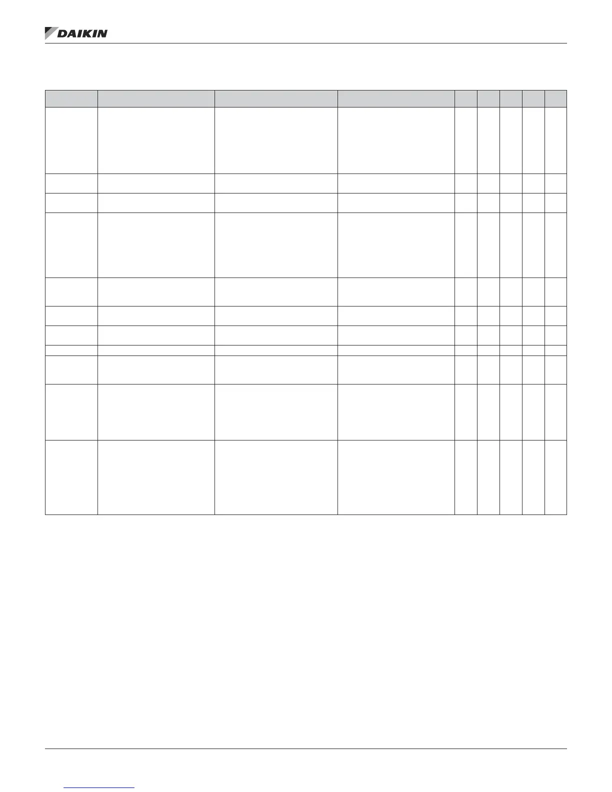
Table 23 continued: Unit Conguration Menu
Conguration
Code Position
Description Values (Default in Bold) Special Condition RTU MPS DPS DPH SCU
17
Return/Exhaust Fan Capacity
Control Method
0=None
1=Tracking
2=Building Pressure
3=Speed
4=OADamper
This position is valid only when
Position 1 = 0 (RTU) or Position 1
= 2 (MPS).
A value of 1 is only valid if Position
16=1 through 5.
A value of 2 or 3 is only valid if
Position 16 = 1 through A.
● ● ● ●
18 Second Duct Pressure Sensor
0=No
1= Yes
● ●
19 Entering Fan Temp Sensor
0=No
1=Yes
● ● ● ●
20 Energy Recovery
0=None
1=ConstSpdWhl/NoRH
2=VarSpdWhl/Danfoss
3=VarSpdWhl/MD2
4=VarSpdWhl/MD3
5=VarSpdWhl/ABB
6=ConstSpdWhl/wRH
This position is valid only when
Position 1 = 0 (RTU) or Position 1
= 2 (MPS).
● ● ● ●
21 Cooling Circuit Type
0=Individual
1=2,3 or 4 Circ. Water Condenser
2=2 Circ. Air Condenser
Values 0 and 1 are valid only when
Position 1 = 1 (SCU)
● ● ● ● ●
22 Head Pressure Control
0=No
1=Yes
This position is valid only when
Position 1 = 1 (SCU).
●
23 Bypass Valve Control
0=Slave
1=Bypass
This position is valid only when
Position 1 = 1 (SCU).
●
24, 25, 26 Unit Size Three digits (default 050) ● ● ● ● ●
27 Refrigerant Type
0=R22
1=R407C
2=R410A
● ● ● ● ●
28 Reheat Type
0=None
1=StgHG
2=ModHG
3=StdHtRht
4=ModLSC
5=ModHG&LSC
● ● ● ●
29 Unit Voltage
0=208/60Hz
1=230/60Hz
2=460/60Hz
3=575/60Hz
4=208/50Hz
5=230/50Hz
6=460/50Hz
7=575/50Hz
● ● ● ● ●
unIT ConfIguraTIon seTup Menu
www.DaikinApplied.com 43 IM 919-3 • MICROTECH III CONTROLLER