SiBE05-722EE Outdoor Unit
Printed Circuit Board Connector Wiring Diagram 27
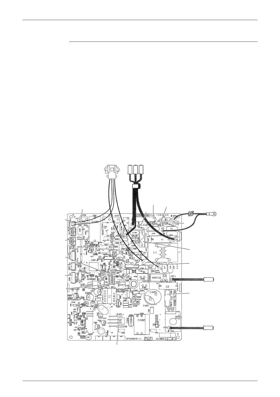
2.4 RXS25/35L3V1B
Main PCB (PCB1)
1) S20 Connector for electronic expansion valve coil
2) S30 Connector for compressor motor
3) S40 Connector for overload protector
4) S50 Connector for magnetic relay
5) S71 Connector for DC fan motor
6) S80 Connector for four way valve coil
7) S90 Connector for thermistors
(outdoor temperature, outdoor heat exchanger, discharge pipe)
8) E1, E2 Terminal for earth wire
9) HL1, HN1, S Connector for terminal board
10)HR1, HR2 Connector for reactor
11)FU1, FU2 Fuse (3.15 A, 250 V)
12)FU3 Fuse (20 A, 250 V)
13)LED A LED for service monitor (green)
14)V2, V3, V150 Varistor
FU3
S, HL1, HN1
FU1
FU2
S30
S40
S90
S20
LED A
S50
S80
S71
HR1
HR2
V2
E1, E2
V150
V3
2P383853-2
 Loading...