13 Unit installation
Installation and operation manual
26
SV1A25AJV1B+SV4~8A14AJV1B
VRV 5 safety valve unit
4P709466-1 – 2023.09
d Suspension bolt
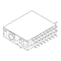
e SV unit
4 Secure the unit by tightening the nut and double nut.
5 Level the unit at all 4 corners by turning the double nuts, the
long nuts or the turnbuckles. Use a level or water-filled vinyl
tube to measure if the unit hangs level. A deviation of maximum
1 degree is allowed in the direction of the drain socket and
away from the switch box.
NOTICE
If the unit is installed at a bigger angle than allowed, water
may drip from the unit.
a Level
b Water-filled vinyl tube
a Drain socket
b Switch box
13.4.2 To connect the drain piping
NOTICE
Incorrect connection of the drain hose might cause leaks,
and damage the installation space and surroundings.
1 Push the drain hose as far as possible over the drain pipe
connection.
a Drain pipe connection (attached to the unit)
b Drain hose (accessory)
2 Position the metal clamp around the drain hose, as close to the
unit as possible.
3 Tighten the metal clamp and bend the tip of the metal clamp so
that the large, self-adhesive sealing pad (accessory) will not be
forced outwards when applied.
c Metal clamp (accessory)
4 Check if the water drains correctly.
▪ Open the inspection hole by removing the inspection hole
cover.
▪ Gradually add water through the inspection hole.
▪ Verify that the water flows through the drain hose and check
for water leaks.
▪ Close the inspection hole.
5 Wind the large, self-adhesive sealing pad (accessory) around
the metal clamp and drain hose.
Note: Start on the screw part of the metal clamp, work your way
around the clamp and end overlapping your starting point.
a Drain pipe connection (attached to the unit)
b Drain hose (accessory)
c Metal clamp (accessory)
d Large, self-adhesive sealing pad (accessory)
6 Connect the drain piping to the drain hose.
e Drain piping (field supply)
 Loading...
