15 Electrical installation
Installation and operation manual
33
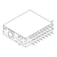
SV1A25AJV1B+SV4~8A14AJV1B
VRV 5 safety valve unit
4P709466-1 – 2023.09
a Insulation tube (field supply)
b Tape (field supply)
c Insulation tube (SV unit)
d Adherence surface
e SV unit
1 Install an insulation tube (a) over the pipe and against the
insulation tube (c) on the SV unit.
2 Apply tape (b) to close the seam.
To insulate the header and branch pipes (extra insulation)
Depending on ambient conditions (see "14.2.3 Refrigerant piping
insulation"[431]), it can be required to add extra insulation material.
Make sure that the insulation is properly mounted over the header
and branch pipes of the unit as shown in the image below. In order
to level out the difference in thickness, an extra insulation tube must
be installed over the insulation tube coming out of the unit. Always
use tape (field supply) to prevent air gaps in the seam between the
insulation tubes.
a Insulation tube (extra thick)(field supply)
b Tape (field supply)
c Insulation tube (SV unit)
d Adherence surface
e SV unit
f Insulation tube for levelling out thickness (field supply)
1 Install an insulation tube (a) over the pipe and against the
insulation tube (c) on the SV unit.
2 Attach an extra layer of insulation tube (f) to level out the
thickness.
3 Apply tape (b) to close the seam.
15 Electrical installation
CAUTION
See "2 Specific installer safety instructions" [4 4] to make
sure this installation complies with all safety regulations.
15.1 Specifications of standard wiring
components
NOTICE
We recommend using solid (single-core) wires. If stranded
wires are used, slightly twist the strands to consolidate the
end of the conductor for either direct use in the terminal
clamp or insertion in a round crimp-style terminal. Details
are described in "Guidelines when connecting the electrical
wiring" in the installer reference guide.
Field wiring consists of:
▪ power supply wiring (including earth),
▪ DIII interconnection wiring between units.
NOTICE
▪ Keep the power line and transmission line apart from
each other. Transmission wiring and power supply
wiring may cross, but may NOT run parallel.
▪ In order to avoid any electrical interference, the
distance between both wirings should ALWAYS be at
least 50mm.
Component Units
SV1A SV4A SV6A SV8A
Power supply
cable
MCA
(a)
0.1A 0.2A 0.3A 0.3A
Voltage 220-240V
Phase 1~
Frequency 50Hz
Wire size Must comply with national wiring
regulation.
3-core cable
Wire size based on the rated
current, but not less than 0.5mm².
Interconnection
wiring
Voltage 220-240V
Wire size Only use harmonised wire
providing double insulation and
suitable for the applicable voltage.
2-core cable
0.75mm²-1.5mm²
Recommended field fuse 6A
Residual current device Must comply with national wiring
regulation.
(a)
MCA=Minimum circuit ampacity. Stated values are maximum
values.
Power supply wiring
The power supply wiring must be protected with the required safety
devices, i.e. a main switch, a slow blow fuse on each phase and an
earth leakage protector in accordance with the applicable legislation.
Selection and sizing of the wiring should be done in accordance with
the applicable legislation based on the information mentioned in the
table above.
Interconnection wiring
The interconnection wiring outside the unit should be wrapped and
routed together with the field piping. See "15.4To finish the electrical
wiring"[436] for more information.
Selection and sizing of the wiring should be done in accordance with
the applicable legislation based on the information mentioned in the
table above.
Interconnection wiring specification and limits
(a)
Maximum wiring length between SV unit and indoor
units
1000m
Maximum wiring length between SV unit and
outdoor unit
1000m
Maximum wiring length between SV units 1000m
Total wiring length 2000m
(a)
If the total interconnection wiring exceeds these limits,
communication errors might occur.
Up to 16 branches are possible for unit-unit cabling. No secondary
branching are allowed after any interconnection wire branching.
 Loading...
