15 Electrical installation
Installation and operation manual
34
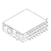
SV1A25AJV1B+SV4~8A14AJV1B
VRV 5 safety valve unit
4P709466-1 – 2023.09
a Outdoor unit
b Indoor unit + SV unit
c Main line
d Branch line 1
e Branch line 2
f Branch line 3
g No branch is allowed after branch
h Central user interface (etc. …)
A Outdoor/indoor interconnection wiring
B Master/slave interconnection wiring
15.2 Connecting the electrical wiring
Use the following methods for installing wires:
Wire type Installation method
Single-core wire
Or
Stranded conductor
wire twisted to "solid-
like" connection
a Curled wire (single-core or twisted
stranded conductor wire)
b Screw
c Flat washer
Stranded conductor
wire with round crimp-
style terminal
a Terminal
b Screw
c Flat washer
Allowed
NOT allowed
For earth connections, use the following method:
Wire type Installation method
Single-core wire
Or
Stranded conductor
wire twisted to "solid-
like" connection
a Clockwise curled wire (single-core or
twisted stranded conductor wire)
b Screw
c Spring washer
d Flat washer
e Coupling washer
f Sheet metal
15.3 To connect the electrical wiring
NOTICE
▪ Follow the wiring diagram (delivered with the unit,
located at the inside of the service cover).
▪ For instructions on how to connect the optional
equipment, see the installation manual delivered with
the optional equipment.
▪ Make sure the electrical wiring does NOT obstruct
proper reattachment of the service cover.
1 Remove the service cover. See "13.3.2To open the unit"[425].
2 Strip insulation from the wires.
a Strip wire end to this point
b Excessive strip length may cause electrical shock or
leakage
Allowed
Not allowed
3 Connect the interconnection wiring as follows:
Connection for SV4A~SV8A
▪ Connect the terminals F1/F2 (TO IN/D) on the control PCB
in the outdoor unit's switch box to the terminals F1/F2
(Outdoor unit) on terminal block X2M of the first SV unit.
See also the installation manual delivered with the outdoor
unit.
▪ In case of multiple SV units in the system that are connected
to the same interconnection wiring branch line, connect the
terminals F1/F2 (SV unit) on terminal block X2M of the first
SV unit to the terminals F1/F2 (Outdoor unit) on terminal
block X2M on the second SV unit. Repeat the same
procedure for further SV units, where each time the
terminals F1/F2 (SV unit) on terminal block X2M on the n
th
SV unit are connected to the terminals F1/F2 (Outdoor unit)
on terminal block X2M on the (n+1)
th
SV unit.
 Loading...
