Control Equipment Conguration
12
c. Click the drop-down menu in lower-right corner, select TCP/IP, and click Open.
d. Enter the controller’s IP address in the free-text box then click Connect to
interface with the controller. DDMS controller default IP address: 172.16.192.25
4. After installation and setup, follow the steps below to congure the sign. Any
reference to the ACP is interchangeable with LCD Simulator.
Logging In
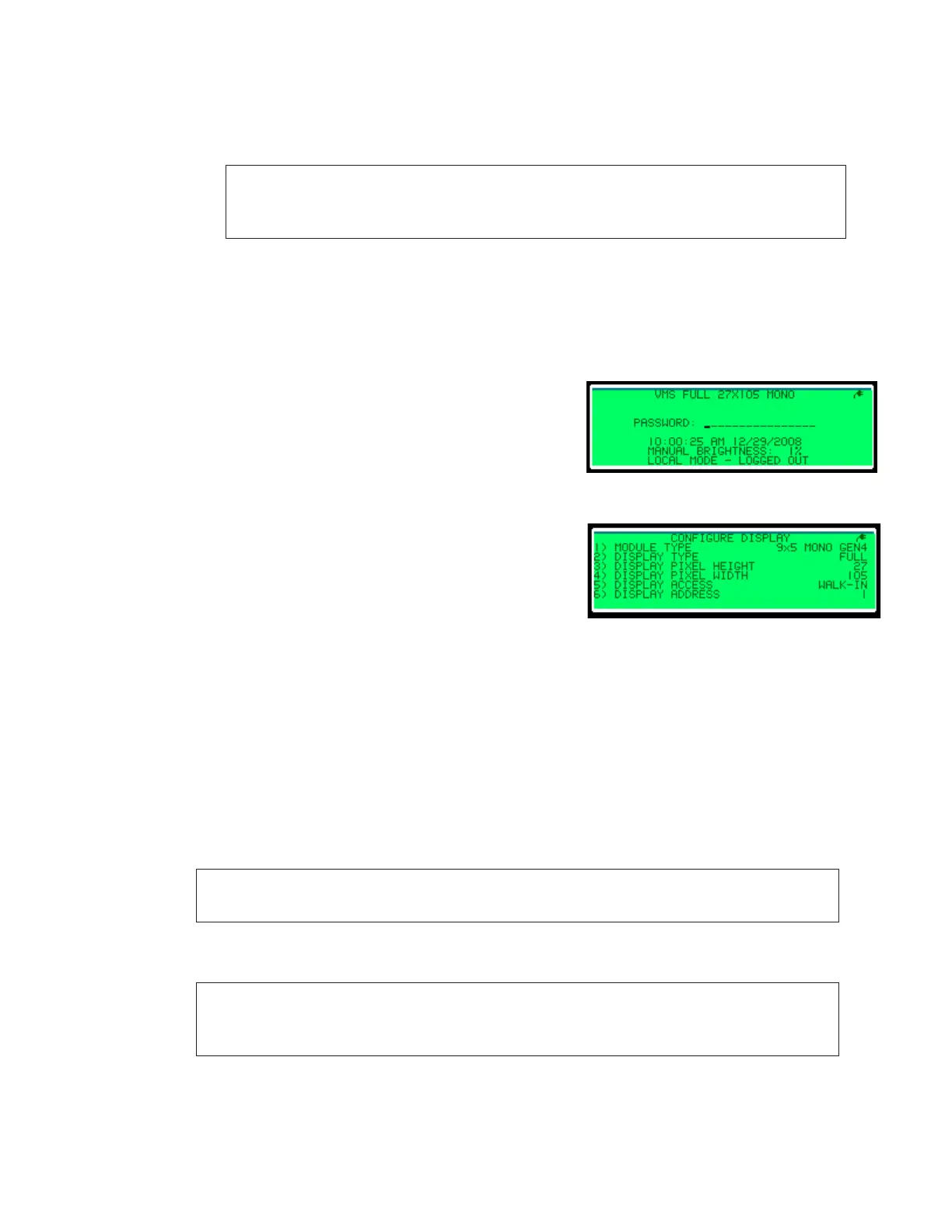
1. Push the Local/Remote toggle switch; the Local Mode menu opens. Refer to Figure 6.
2. Press Enter on the keypad. The Main Menu opens.
LED Panel Conguration
1. Press 4 to open the Conguration menu.
2. Press 1 to open the System Conguration menu.
3. Press 1 to open the Congure Display menu. Refer
to Figure 7.
4. Press 1 to open the Module Type menu.
5. Press 1 for Monochrome (amber LED panels), or
press 2 for Red-Green (tricolor LED panels).
6. Press 1 for Gen 4.
7. Press 1 for 7 x 5 modules.
8. Select 66 mm LED panels from the menu. The ACP returns to the Congure Display
menu.
9. Press 2 to open the Display Type menu.
10. Press 2 for Line. The ACP returns to the Congure Display menu.
11. Press 3 to open the Display Pixel Height menu.
12. Type the height of the grouping of LED panels in the set and press Enter. The ACP
returns to the Congure Display menu.
Note: In Figure 8, the height of the grouping of LED panels is 21. (display pixel
height = 7 pixels high per LED panel × 3 LED panels high).
13. Type the width of the grouping of LED panels in the set and press Enter. The ACP
returns to the Congure Display menu.
Note: In Figure 8, the width of the grouping of LED panels is 20. In Figure 9, the
width of the grouping of LED panels is also 20. (display pixel width = 20 pixels
wide per LED panel).
Note: The computer connected to the controller will need to be on the same
subnet.
Example: 172.16.192.24
Figure 6: Local Mode—logged out
Figure 7: Congure Display
 Loading...
