Components
4
Fiber-to-Wire Enclosure
The ber-to-wire enclosure is used with the ber option. The enclosure contains the
product board which converts ber cable to copper wire, as required by the LED
panel(s).
LED Panel
The LED panel contains groups of modules. The pixels
display messages on the sign.
Module
A module is a replaceable unit consisting of a display
panel with clusters of LEDs, called pixels. The pixels display
messages on the LED panel(s). Refer to Figure 3.
Each module contains drive electronics that receive
data packets from the distribution board and lights the
appropriate pixels at the correct dimming level.
Outlets
The GFCI and control equipment outlets are located
near the panelboard.
Power Entry Box
The power entry box is located inside the DDMS cabinet.
On a single door cabinet, it is located behind the door.
On a cabinet with two doors, it is located behind the door on the
side designated as rear. Utility power terminates in the power entry
box.
Power Supply Assembly
Each DDMS set contains two power supply assemblies. Each
power supply assembly contains one power supply and one
isolation board.
Power Supply
The power supplies provide voltage to power the LED panels.
Multiple power supplies provide power redundancy. If one power
supply fails, the other is capable of supporting the full power load,
which prevents power failure to the modules.
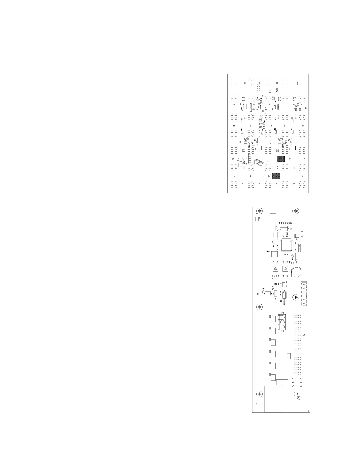
Isolation Board
One isolation board mounts to each power supply; refer to
Figure 4. The isolation board prevents a shorted output on one
power supply from affecting the output of the other power supply
assembly.
The isolation board routes 120 VAC from the panelboard to the
power input of the power supply, and then routes DC output from
the power supply to the DC circuit breakers and ground terminal
blocks on the DC terminal assembly.
Isolation board diagnostics includes power supply data sent to the
DDMS controller about output voltage.
Figure 3: Module (Front View)
Figure 4: Isolation Board
 Loading...
