14 Spyder2 User’s Manual
03-032-10091-06 Teledyne DALSA
Low Pi xel r eset
EXSYNC (Triggers Line Readout)
EXSYNC is an optional input signal that can be used to trigger the line readout rate. This
camera uses the
falling edge of EXSYNC to trigger line readout.
Note: EXSYNC should not be clocked faster than the camera’s specified maximum line
rate. The camera i gnores the EXSYN C pul se unti l i t has completed reading the l ast l ine
out.
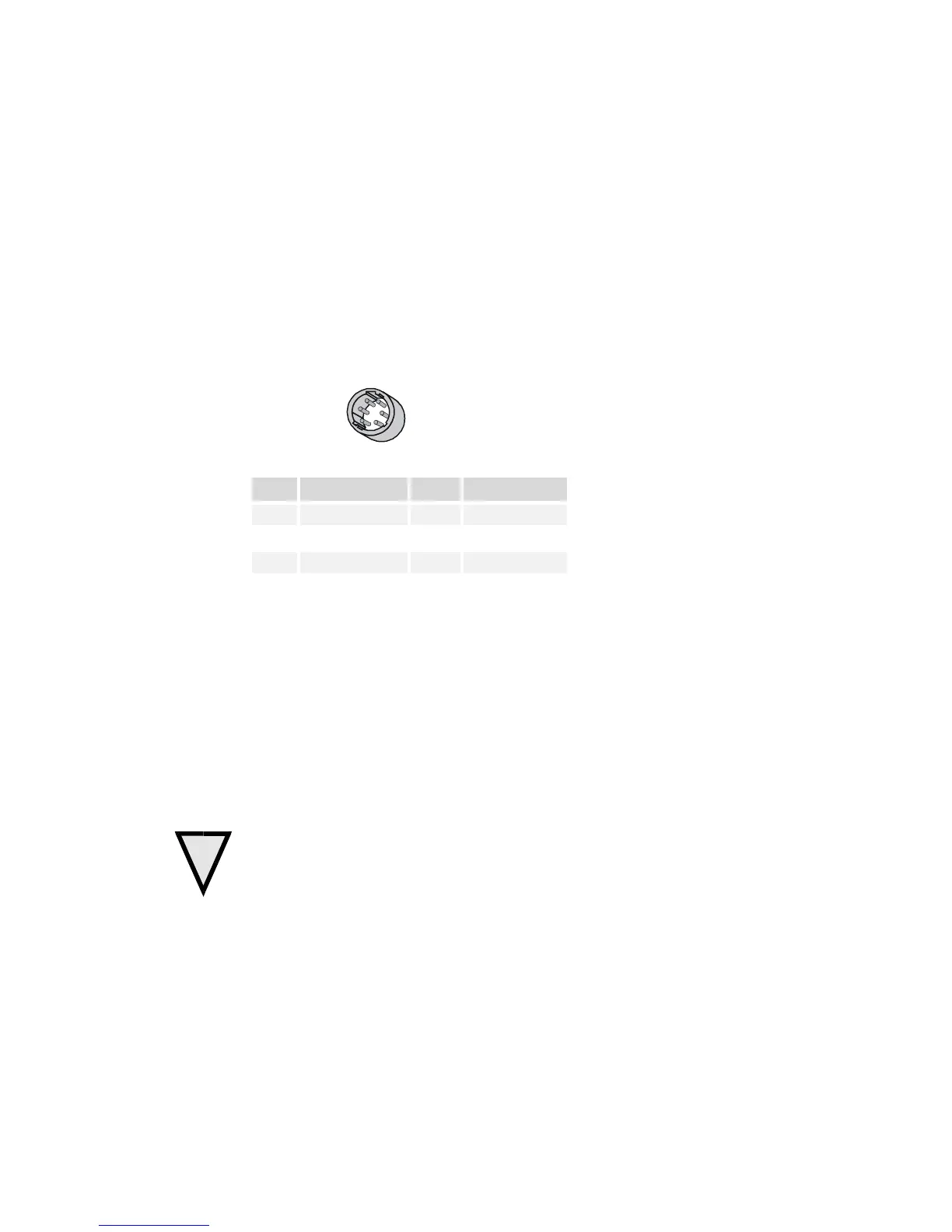
2.2.3 Power Connector
Hirose 6-pin Circular Male
5
4
6
2
3
1
Mat ing Par t : HIRO SE
HR10A-7P-6S
Pin Description Pin Description
1 +12V to +15V 4 GND
3 +12V to +15V 6 GND
The cam er a requi res a single v ol tage input (+12 V to +15 V). The camera meet s al l
performance specifications using standard switching power supplies, although well-
regul ated li near supplies prov i de optimum perfor mance. See the Per formance
Specifications for current requirements.
When setting up the camera’ s pow er suppl i es fol l ow these guidel i nes:
• Protect the camera with a fast-blow fuse betw een pow er supply and camera.
• Do not use the shield on a multi-conductor cable for ground.
• Keep l eads as short as possible to r educe vol tage drop.
Note: Performance specifications are not guaranteed if your power supply does not meet
these requi rements
WARNING: It is extremely important that you apply the appropriate voltages to your camera.
Incorrect voltages will damage the camera. Protect the camera with a fast-blow fuse between
power supply and camera.
Visit the www.mv.dal sa.com Web site for a list of companies that make power supplies
that meet the camera’s requi r em ents. The compani es listed should not be considered the
only choices.