W
Willie SchneiderAug 5, 2025
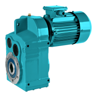
Why is my DANA BREVINI E Engine gearbox not working in low speeds/frequencies?
- MMichael MyersAug 5, 2025
If your DANA Engine gearbox isn't working well at low speeds or frequencies, it may be due to the frequency inverter operating at very low frequencies, which requires optimized inverter and motor parameters. Also, the gearbox efficiency might vary significantly, especially in worm-gearboxes. It's recommended to operate worm-gearboxes between 20-70 Hz and helical gear boxes between 10-70 Hz. Consider using a higher power motor and frequency inverter, or adjust the gearbox ratio to work within the recommended frequency range.