Levels
Selecting "Levels" and pushing the encoder enters the sub-menu.
Turning the encoder one detent to the right and back toggles between
channel A and B.
Pushing the encoder exits the sub-menu.
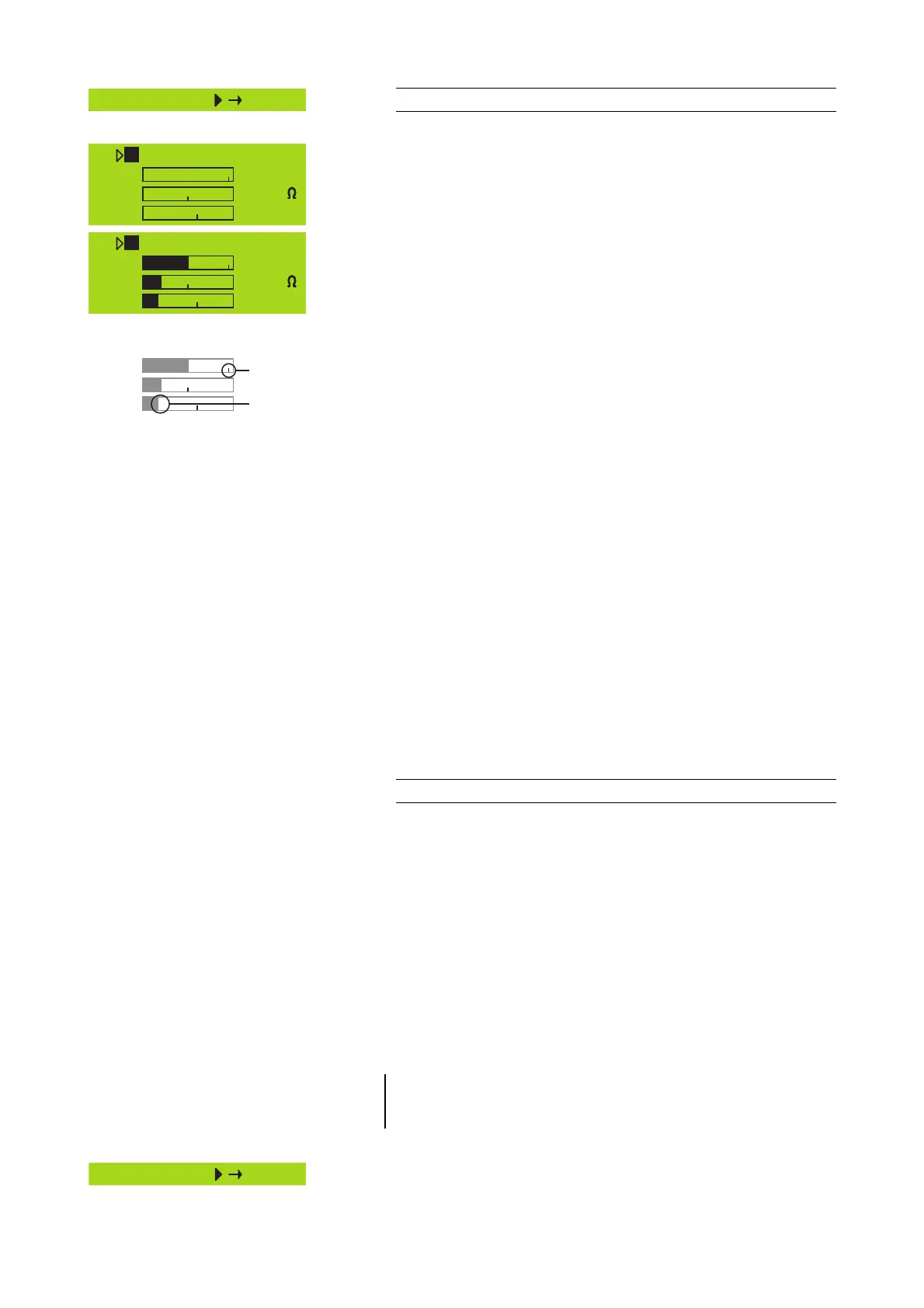
In the "Levels screen" the following values are displayed as bar graphs
and/or as numeric values:
Input gain/Temperature of the device
In the first line the input gain setting of the respective channel is
displayed as the numeric value in dB and the temperature of the either
amplifier or power supply (whichever value is higher).
Input
Input signal level as bar graph and the numeric value is displayed in
dBu. The small vertical mark [A] represents the threshold of input level
where an input overload occurs (red OVL LED). The colon [B] acts as a
peak hold for 1 s.
Headr. (Headroom)
The bar graph shows the relationship between modulation and gain
reduction (GR). The small vertical mark [A] indicates the gain reduction
threshold (0 dB headroom), the colon [B] acts as a peak hold for 1 s. The
gain reduction (GR) LED (yellow) indicates a gain reduction of more than
3 dB.
Impedance Z
The impedance of the loudspeaker(s) presented to the output of the
D12, displayed only as a numeric value in ohms. The value is measured
with the actual output signal and may therefore vary with its spectral
content. The measurement range reaches from 0 ohms (short circuit) to
255 ohms (open loop, I = 0, Z ⇒ ∞). When the signal is too low the
maximum of 255 ohms will be displayed.
Power
The actual output power, displayed as bar graph and as a numeric
value in watts, the colon [B] acts as a peak hold for 1 s.
System Check
System Check is a powerful and convenient tool to check the condition
of either a single d&b loudspeaker or a complete d&b sound system
driven by the D12. It is preferably used in conjunction with the d&b
Remote network and the ROPE C software (from version 1.1.3).
System Check uses the amplifiers' capability to measure the impedance
connected to its outputs using a sine wave signal created by the DSP
section of its controller.
System Check is related to the Load Monitoring feature of the D12.
Both functions share the same measuring principle and impedance
reference values. While System Check uses a single measuring run Load
Monitoring supervises continuously by recurring measurements. System
Check creates a detailed report about the connected loads whereas
Load Monitoring is confined to an error message if a fault is detected.
Note:
This section describes the System Check menus within the D12. A more
detailed description of System Check and its application is given in the
technical information TI 360 (d&b code D5360.E.).
Selecting "System Check" and pushing the encoder enters the sub-
menu.
D12 Software manual (Firmware V2.x.x) (5.2EN) Page 14 of 36
Fig. 7: D12 Levels
Ch A -3.0dB 36°C
Input -80dBu
Headr. Z 255
Power 0W
Ch B +0.0dB 36°C
Input : -30dBu
Headr. : Z 7
Power : 30W
Input :
Headr. :
Power :
[A]
[B]

 Loading...


