D
GB
F
E
PT
I
TR
Ru
© Danfoss | Climate Solutions | 2023.07
AQ453249013813en-000201| 11
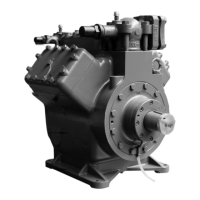
4| Compressor assembly
4.7 Pipes
Pipes and system components must be clean and dry inside and free of scale, swarf and layers of
rust and phosphate. Only use air-tight parts.
Lay pipes correctly. Suitable vibration compensators must be provided to prevent pipes being cracked
and broken by severe vibrations.
Ensure a proper oil return.
Keep pressure losses to an absolute minimum.
The pipe connections, if installed, have stepped internal diameters so
that pipes with standard millimetre and inch dimensions can be used.
The connection diameters of the shut-off valves are designed for
maximum compressor output. The requiredpipe cross-section
must be matched to the capacity. The same applies for non-return
valves.
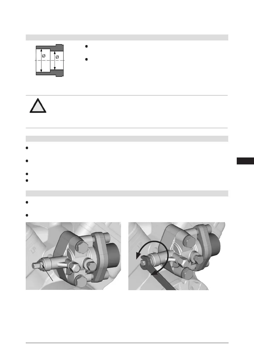
Fig. 10: Stepped
internal diameters
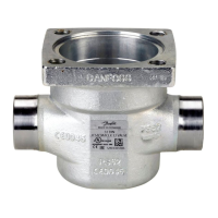
4.6 Pipe connections
Valve spindle seal
4.8 Operating the shut-off valves
Before opening or closing the shut-off valve, release the valve spindle seal by approx. ¼ of a turn
counter-clockwise.
After activating the shut-off valve, re-tighten the adjustable valve spindle seal clockwise.
Fig. 11
Fig. 12
Release
Tighten
ATTENTION Overheating can damage the valve.
Therefore, remove the pipe supports from the valve before
soldering.
Solder only using inert gas to inhibit oxidation products (scale).
 Loading...