D
GB
F
E
PT
I
TR
Ru
© Danfoss | Climate Solutions | 2023.07
AQ453249013813en-000201| 13
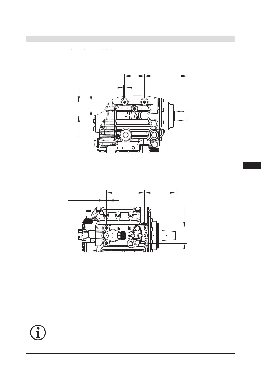
Fig. 15
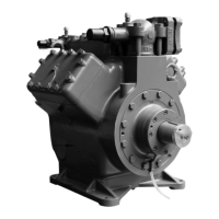
The M10 threads in the housing can be used for screwing on attachments and bracing the
compressor.
• Maximum load on the screw connection = 6 g-force
•Maximumtighteningtorqueofthescrews=60Nmwithminimumscrew-indepth=20mm
andfrictioncoefcient=µ0,15.
• Maximum screw-in depth 25 mm.
• Usable screws up to strength class 10.9.
Incaseofscrew-indepthslessthan15mmorlowerfrictioncoefcientsthanµ=0.15,thetightening
torquesandmaximumloadmustbereduced.
INFO
If the M10 threads are used as additional bracing, installation is
overdetermined. It must be ensured that the compressor housing is not
distorted during installation. The specifications of the motor / chassis
manufacturer are mandatory.
Mounting thread only on this side of the compressor available.
4.11 Characteristics for K1 special housing
4| Compressor assembly
167,8
50
170
168,5
1.0851-13992.0 0c
Part-No.
F
E
D
C
A
F
E
D
C
4
1
A
B
5
6
7
8
1
2
34
5
6
78
Zeichn.-Nr. / Drawing-no. :
B
3
Dok-ID:
A. Layh
Maßstab /
±0.1
über / above
Freigabe / Approved
z
Der Lieferant muss sicherstellen, dass die Ware
in einwandfreiem Zustand angeliefert wird
(Korrosionsschutz, Verpackung für sicheren
A. Layh
Allgemeintoleranzen / General tolerances
Drawing-No.
bis / up to
2
yx w u t s
-
packaging for safe transportation).
A. Layh
1.0851-13983.0 0l
in proper conditions (corrosion prevention,
model or design.
DIN ISO 2768-mK-E
Ersatz für / replacement for:
The supplier has to ensure the delivery of parts
Transport).
prohibited. Offenders will be held liable for the
Dimension Passung / Clearance
-
Baumustergeprüft / Type examination:
-
K.-Auftrag / C.-Task:
Projektleiter / Project leader:
120
400
±0.5
0.5
6
08017
BOCK GmbH - Benzstraße 7 - 72636 Frickenhausen - Germany - www.bock.de
18.08.2021
-
-
-
Bearb. / EditedDatum / Date
payment of damages. All rights reserved in the event
Änd.-Nr. / Mod-No.
Werkstoff (Zeile 2+3 alternativ) /
Unbemaßte Radien / Undimensioned radii:
Base part, Raw part:
-
Geprüft / Appr.
Name
Oberflächenbehandlung, Härte / Treatment of surface, Hardness:
-
Material (Line 2+3 alternative):
Ausgangsteil, Rohteil /
Workpiece edges
DIN ISO 13715
Erstellt / Drawn
J. Faßbender
S. Büttner
Datum / Date
1/4
18.08.2021
18.08.2021
Werkstückkanten /
Page:
400
Benennung / Description:
±0.8
1000
30 6
-
±0.3
12030
-
Blatt /
±0.2
of the grant of a patent, utility
/
DIN EN ISO 1302
Zust. / Rev.
Gußtoleranzen / General casting tolerances:
Gewicht / Weight: (kg)
Zeichnungs-Nr. /
Indication of surface texture
Geprüft / Verified
J. Faßbender
C - FKX40/655 K
Rz 25
Rz 160
Rz 1,6
Rz 16
Rz 63 Rz 6,3
28.02.22
.0
-
-
%13992
Nein / No
Scale:
Rz 12,5
26.07.2211612
M. Schaich
114810a | Betrifft Blatt 2
V. Polizzi
0c | Betrifft Blatt 3
0b | K1-Ausführungen aufgenommen S. Büttner
30.09.22
11738
-
K - FKX40/655 K
0851
Kunde / Customer:
1.
A. Layh
Weitergabe sowie Vervielfältigung dieses Dokuments,
Verwertung und Mitteilung seines Inhalts sind ver-
boten, soweit nicht ausdrücklich gestattet. Zuwider-
handlungen verpflichten zu Schadenersatz. Alle
Rechte für den Fall der Patent-, Gebrauchsmuster-
oder Geschmacksmustereintragung vorbehalten.
The reproduction, distribution and utilization of this
document as well as the communication of its
contents to others without express authorization is
Maß
Oberflächenangaben /
Teile-Nr. /
358912
Änderungen vorbehalten
Subject to change without notice
Maße in mm
Dimensions in mm
( ) K + K1 Ausführung
( ) K + K1 version
Fahrzeugverdichter / Vehicle Compressor
Typ /
type
Teile-Nr. /
part-no.
Typ /
type
Teile-Nr. /
part-no.
Typ /
type
Teile-Nr. /
part-no.
Typ /
type
Teile-Nr. /
part-no.
FKX40/390 N 13985 FKX40/390 K 13986 FKX40/390 K1 14055 FKX40/390 TK 14343
FKX40/470 N 13987 FKX40/470 K 13988 FKX40/470 K1 14056 FKX40/470 TK 14344
FKX40/560 N 13989 FKX40/560 K 13990 FKX40/560 K1 14057 FKX40/560 TK 14345
FKX40/655 N 13991 FKX40/655 K 13992 FKX40/655 K1 14058 FKX40/655 TK 14346
FKX40/755 K 13999 FKX40/755 K1 14059
Massenschwerpunkt
Centre of gravity
Anschlüsse /
Connections
FKX40/390
N+TK
FKX40/470+560
N+TK
FKX40/655
N+TK
FKX40/
390-755 K + K1
SV
Saugabsperrventil, Rohr (L)*
mm - Zoll /
mm - inch
28 – 1 1/8 “ 35 – 1 3/8 “ 35 – 1 3/8 “
mit Staubschutz
verschlossen /
closed with
dust cover
Suction line valve, tube (L)*
DV
Druckabsperrventil, Rohr (L)*
mm - Zoll /
mm - inch
22 – 7/8 “
28 – 1 1/8 “ 35 – 1 3/8 “
Discharge line valve, tube (L)*
A
Anschluss Saugseite, nicht absperrbar
Zoll / inch
1/8“ NPTF
Connection suction side, not lockable
A1
Anschluss Saugseite, absperrbar
Zoll / inch
7/16“ UNF
Connection suction side, lockable
B
Anschluss Druckseite, nicht absperrbar
Zoll / inch
1/8“ NPTF
Connection discharge side, not lockable
B1
Anschluss Druckseite, absperrbar
Zoll / inch
7/16“ UNF
Connection discharge side, lockable
C
Anschluss Öldrucksicherheitsschalter OIL
Zoll / inch
1/8“ NPTF
Connection oil pressure safety switch OIL
D
Anschluss Öldrucksicherheitsschalter LP
Zoll / inch
1/8“ NPTF
Connection oil pressure safety switch LP
E
Anschluss Öldruckmanometer
Zoll / inch
1/8“ NPTF
Connection oil pressure gauge
F
Ölablass
Zoll / inch
1/4“ NPTF
Oil drain
G
Opt. Anschlussmöglichkeit Ölsumpfheizung 1)
-
-
Opt. connection oil sump heater 1)
H
Stopfen Ölfüllung
Zoll / inch
1/4“ NPTF
Oil charge plug
K
Schauglas
Zoll / inch
2 x 1 1/8 “ – 18 UNEF
Sight glass
L
Anschluss Wärmeschutzthermostat
Zoll / inch
1/8“ NPTF
Connection thermal protection thermostat
M
Ölsieb
mm
M22x1,5
Oil filter
SV1
Opt. Anschlussmöglichkeit Saugabsperrventil
-
-
Opt. connection suction line valve
(L)* = Lötanschluss / brazing connection
1) = Nur ab Werk möglich / ony possible ex factory
[ ] TK Ausführung
[ ] TK version
nur bei K1 Ausführung
only for K1 version
6x M8
A5x9 DIN 6888
8x M8
1:5
50
h8
90
148
54
74
110
98
66
40
2
M12x28
100
123,5
60
150
4xM10
Z
5 4
7 8
2 6
3xM10
4xM10x21
L
H
K
F
D
Lecköl-Ablass Schlauch
Leak oil drain hose
130
170
345
253
384
+2
108,5
SV
DV
B1
valve version N+TK-version
Ventilausführung N+TK-Version
A
A1
B
M
C/E
SV1
G
Z
145
369
232
210
+2
13
329
4x
321 (326) [320]
+2
A
B1
B
DV
A1
SV
Ventilausführung K+K1-Version
valve version K+K1-version
72
130
167,8
50
170
168,5
1.0851-13992.0 0c
Part-No.
F
E
D
C
A
F
E
D
C
4
1
A
B
5
6
7
8
1
2
34
5
6
78
Zeichn.-Nr. / Drawing-no. :
B
3
Dok-ID:
A. Layh
Maßstab /
±0.1
über / above
Freigabe / Approved
z
Der Lieferant muss sicherstellen, dass die Ware
in einwandfreiem Zustand angeliefert wird
(Korrosionsschutz, Verpackung für sicheren
A. Layh
Allgemeintoleranzen / General tolerances
Drawing-No.
bis / up to
2
yx w u t s
-
packaging for safe transportation).
A. Layh
1.0851-13983.0 0l
in proper conditions (corrosion prevention,
model or design.
DIN ISO 2768-mK-E
Ersatz für / replacement for:
The supplier has to ensure the delivery of parts
Transport).
prohibited. Offenders will be held liable for the
Dimension Passung / Clearance
-
Baumustergeprüft / Type examination:
-
K.-Auftrag / C.-Task:
Projektleiter / Project leader:
120
400
±0.5
0.5
6
08017
BOCK GmbH - Benzstraße 7 - 72636 Frickenhausen - Germany - www.bock.de
18.08.2021
-
-
-
Bearb. / EditedDatum / Date
payment of damages. All rights reserved in the event
Änd.-Nr. / Mod-No.
Werkstoff (Zeile 2+3 alternativ) /
Unbemaßte Radien / Undimensioned radii:
Base part, Raw part:
-
Geprüft / Appr.
Name
Oberflächenbehandlung, Härte / Treatment of surface, Hardness:
-
Material (Line 2+3 alternative):
Ausgangsteil, Rohteil /
Workpiece edges
DIN ISO 13715
Erstellt / Drawn
J. Faßbender
S. Büttner
Datum / Date
1/4
18.08.2021
18.08.2021
Werkstückkanten /
Page:
400
Benennung / Description:
±0.8
1000
30 6
-
±0.3
12030
-
Blatt /
±0.2
of the grant of a patent, utility
/
DIN EN ISO 1302
Zust. / Rev.
Gußtoleranzen / General casting tolerances:
Gewicht / Weight: (kg)
Zeichnungs-Nr. /
Indication of surface texture
Geprüft / Verified
J. Faßbender
C - FKX40/655 K
Rz 25
Rz 160
Rz 1,6
Rz 16
Rz 63 Rz 6,3
28.02.22
.0
-
-
%13992
Nein / No
Scale:
Rz 12,5
26.07.2211612
M. Schaich
114810a | Betrifft Blatt 2
V. Polizzi
0c | Betrifft Blatt 3
0b | K1-Ausführungen aufgenommen S. Büttner
30.09.22
11738
-
K - FKX40/655 K
0851
Kunde / Customer:
1.
A. Layh
Weitergabe sowie Vervielfältigung dieses Dokuments,
Verwertung und Mitteilung seines Inhalts sind ver-
boten, soweit nicht ausdrücklich gestattet. Zuwider-
handlungen verpflichten zu Schadenersatz. Alle
Rechte für den Fall der Patent-, Gebrauchsmuster-
oder Geschmacksmustereintragung vorbehalten.
The reproduction, distribution and utilization of this
document as well as the communication of its
contents to others without express authorization is
Maß
Oberflächenangaben /
Teile-Nr. /
358912
Änderungen vorbehalten
Subject to change without notice
Maße in mm
Dimensions in mm
( ) K + K1 Ausführung
( ) K + K1 version
Fahrzeugverdichter / Vehicle Compressor
Typ /
type
Teile-Nr. /
part-no.
Typ /
type
Teile-Nr. /
part-no.
Typ /
type
Teile-Nr. /
part-no.
Typ /
type
Teile-Nr. /
part-no.
FKX40/390 N 13985 FKX40/390 K 13986 FKX40/390 K1 14055 FKX40/390 TK 14343
FKX40/470 N 13987 FKX40/470 K 13988 FKX40/470 K1 14056 FKX40/470 TK 14344
FKX40/560 N 13989 FKX40/560 K 13990 FKX40/560 K1 14057 FKX40/560 TK 14345
FKX40/655 N 13991 FKX40/655 K 13992 FKX40/655 K1 14058 FKX40/655 TK 14346
FKX40/755 K 13999 FKX40/755 K1 14059
Massenschwerpunkt
Centre of gravity
Anschlüsse /
Connections
FKX40/390
N+TK
FKX40/470+560
N+TK
FKX40/655
N+TK
FKX40/
390-755 K + K1
SV
Saugabsperrventil, Rohr (L)*
mm - Zoll /
mm - inch
28 – 1 1/8 “ 35 – 1 3/8 “ 35 – 1 3/8 “
mit Staubschutz
verschlossen /
closed with
dust cover
Suction line valve, tube (L)*
DV
Druckabsperrventil, Rohr (L)*
mm - Zoll /
mm - inch
22 – 7/8 “
28 – 1 1/8 “ 35 – 1 3/8 “
Discharge line valve, tube (L)*
A
Anschluss Saugseite, nicht absperrbar
Zoll / inch
1/8“ NPTF
Connection suction side, not lockable
A1
Anschluss Saugseite, absperrbar
Zoll / inch
7/16“ UNF
Connection suction side, lockable
B
Anschluss Druckseite, nicht absperrbar
Zoll / inch
1/8“ NPTF
Connection discharge side, not lockable
B1
Anschluss Druckseite, absperrbar
Zoll / inch
7/16“ UNF
Connection discharge side, lockable
C
Anschluss Öldrucksicherheitsschalter OIL
Zoll / inch
1/8“ NPTF
Connection oil pressure safety switch OIL
D
Anschluss Öldrucksicherheitsschalter LP
Zoll / inch
1/8“ NPTF
Connection oil pressure safety switch LP
E
Anschluss Öldruckmanometer
Zoll / inch
1/8“ NPTF
Connection oil pressure gauge
F
Ölablass
Zoll / inch
1/4“ NPTF
Oil drain
G
Opt. Anschlussmöglichkeit Ölsumpfheizung 1)
-
-
Opt. connection oil sump heater 1)
H
Stopfen Ölfüllung
Zoll / inch
1/4“ NPTF
Oil charge plug
K
Schauglas
Zoll / inch
2 x 1 1/8 “ – 18 UNEF
Sight glass
L
Anschluss Wärmeschutzthermostat
Zoll / inch
1/8“ NPTF
Connection thermal protection thermostat
M
Ölsieb
mm
M22x1,5
Oil filter
SV1
Opt. Anschlussmöglichkeit Saugabsperrventil
-
-
Opt. connection suction line valve
(L)* = Lötanschluss / brazing connection
1) = Nur ab Werk möglich / ony possible ex factory
[ ] TK Ausführung
[ ] TK version
nur bei K1 Ausführung
only for K1 version
6x M8
A5x9 DIN 6888
8x M8
1:5
50
h8
90
148
54
74
110
98
66
40
2
M12x28
100
123,5
60
150
4xM10
Z
5 4
7 8
2 6
3xM10
4xM10x21
L
H
K
F
D
Lecköl-Ablass Schlauch
Leak oil drain hose
130
170
345
253
384
+2
108,5
SV
DV
B1
valve version N+TK-version
Ventilausführung N+TK-Version
A
A1
B
M
C/E
SV1
G
Z
145
369
232
210
+2
13
329
4x
321 (326) [320]
+2
A
B1
B
DV
A1
SV
Ventilausführung K+K1-Version
valve version K+K1-version
 Loading...