6 Piping Connection
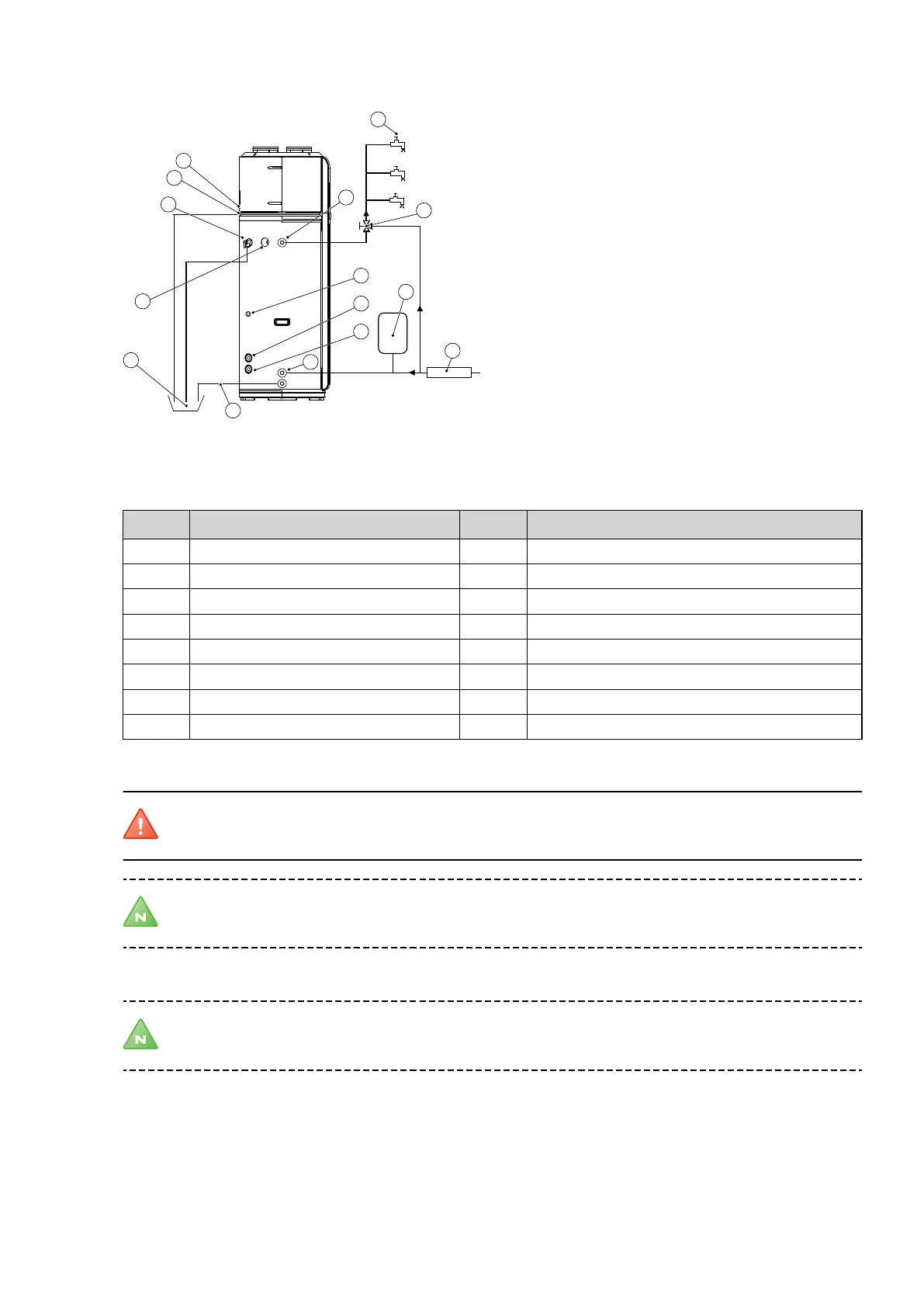
Figure 5. Principal Piping Connection
Position Explanation Position Explanation
1 Upper condensate outlet 12 Valve stem
2 Lower condensate outlet 13 Expansion vessel (if required)
3 Hot water tap 14 Solar water inlet
4 Solar sensor 15 Solar water outlet
5 Drain barrel 16 Drain pipe
8 Temperature and pressure valve 17 Mixing valve
9 Anode rod 27 Water inlet
10 Hot water outlet
Warning! If a solar energy solution is installed, the water temperature can rise very quickly. Preventive
measures must be taken for the piping connections.
Note! If the water pressure is too high (above 5 bars), a pressure reducer should be installed at the water
inlet. This is the installer´s responsibility.
In principle, arrange the water pipes connections as illustrated in the above figure example.
Note! A safety valve should be installed at the water inlet of the unit.
6.1 Water inlet and outlet pipes
The specification of the water inlet or outlet (internal) thread is DN20 (RC3/4”). Pipes must be heat-resistant and
durable.
12 – Installation, Service and User Manual VMGFK202