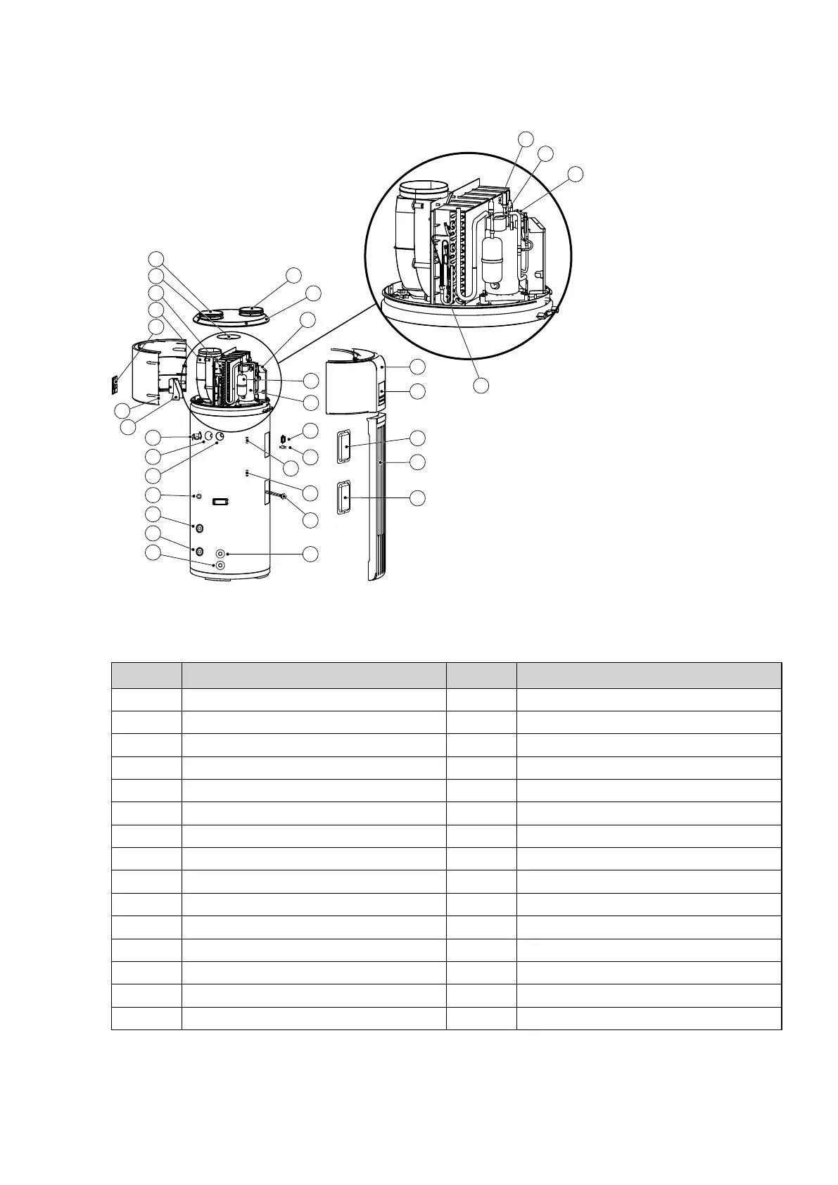
3 Components
The component image below shows diagrammatically how the air source heat pump (from now on also called the
unit) looks inside.
19
6
7
2
1
17
18
3
4
5
16
15
14
13
9
10
8
23
24
22
21
25
12
26
27
11
20
28
33
34
32
31
36
35
Figure 1. Exploded view, unit components
Table 1. Parts Name
Position Description Position Description
1 Air outlet 18 Top cover
2 Filter 19 Electronic control box
3 Evaporator 20 Compressor
4 Fan assy 21 Front cover
5 Junction box cover 22 Display
6 Rear cover 23 Cover (temperature safety function)
7 Junction box 24 Front board
8 Temperature and pressure valve 25 Cover (electrical heater)
9 Anode rod 26 Electrical heater
10 Hot water outlet 27 Water inlet
11 Temperature cut off (TCO) 28 Receiver
12 Manual reset Temperature Cut Off (MTCO) 31 Evaporator pipe temperature sensor (T3)
13 Solar sensor 32 Ambient temperature sensor (T4)
14 Solar water inlet 33 Suction temperature sensor (TH)
15 Solar water outlet 34 Discharge pipe temperature sensor (TP)
Installation, Service and User Manual VMGFK202 – 7