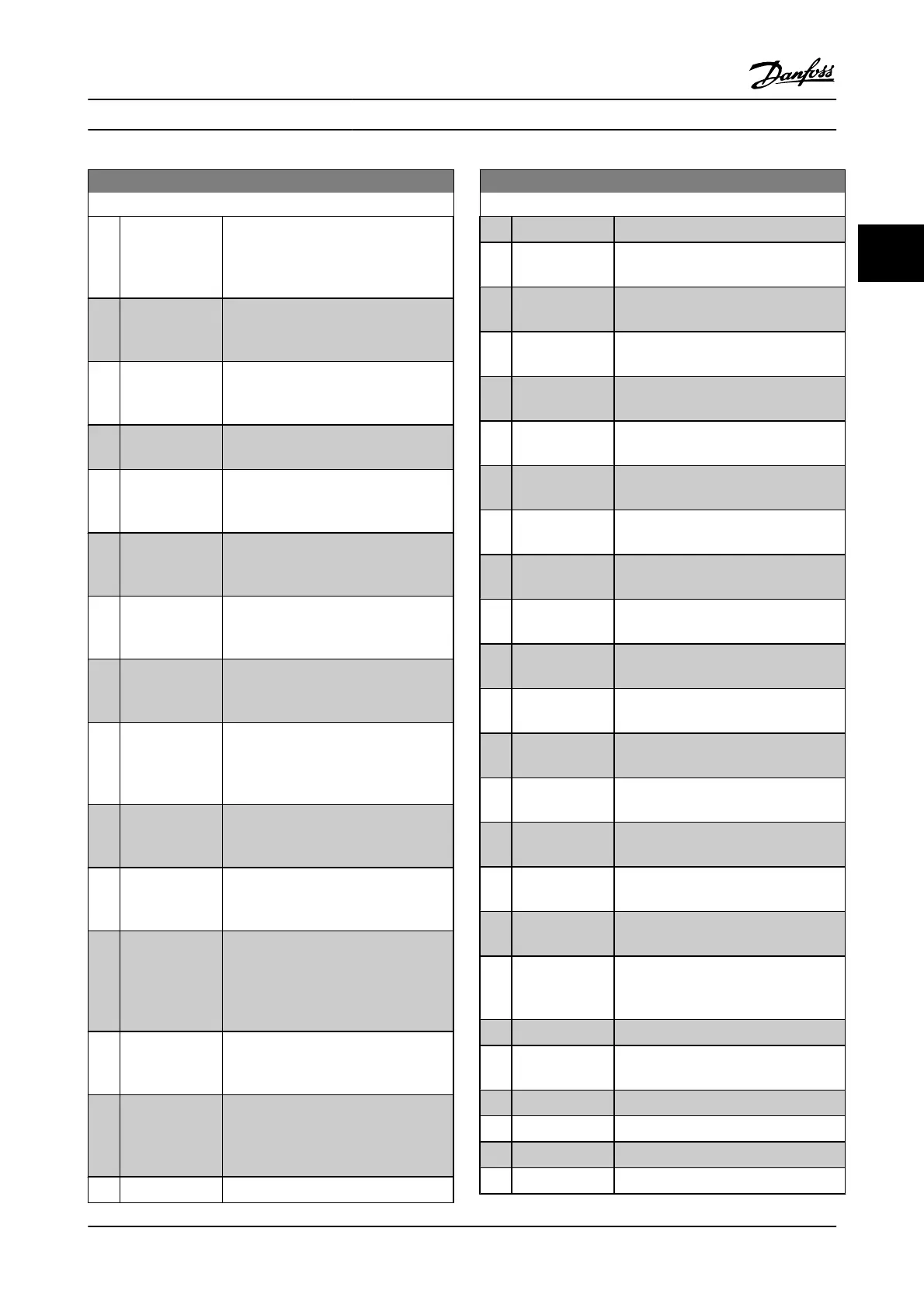
13-01 Start Event
Option: Function:
[5] Torque limit Torque limit [5] The torque limit, set in
4-16 Torque Limit Motor Mode or
4-17 Torque Limit Generator Mode, has
been exceeded.
[6] Current limit Current limit [6] The motor current limit,
set in 4-18 Current Limit, has been
exceeded.
[7] Out of current
range
Out of current range [7] The motor current
is outside the range set in 4-18 Current
Limit.
[8] Below I low Below I low [8] The motor current is lower
than set in 4-50 Warning Current Low.
[9] Above I high Above I high [9] The motor current is
higher than set in 4-51 Warning Current
High.
[10] Out of speed
range
Out of speed range [10] The speed is
outside the range set in 4-52 Warning
Speed Low and 4-53 Warning Speed High.
[11] Below speed low Below speed low [11] The output speed is
lower than the setting in 4-52 Warning
Speed Low.
[12] Above speed
high
Above speed high [12] The output speed is
higher than the setting in 4-53 Warning
Speed High.
[13] Out of feedb.
range
Out of feedb. Range [13] The feedback is
outside the range set in 4-56 Warning
Feedback Low and 4-57 Warning Feedback
High.
[14] Below feedb. low Below feedb. Low [14] The feedback is
below the limit set in 4-56 Warning
Feedback Low.
[15] Above feedb.
high
Above feedb. High [15] The feedback is
above the limit set in 4-57 Warning
Feedback High.
[16] Thermal warning Thermal warning [16]:the thermal warning
turns on when the temperature exceeds
the limit in the motor, the adjustable
frequency drive, the brake resistor or the
thermistor.
[17] Mains out of
range
AC line voltage out of range [17] The AC
line voltage is outside the specified
voltage range.
[18] Reverse Reversing [18] The output is high when
the adjustable frequency drive is running
counter-clockwise (the logical product of
the status bits “running” AND “reverse”).
[19] Warning Warning
[19] A warning is active.
13-01 Start Event
Option: Function:
[20] Alarm (trip) Alarm (trip) [20] A (trip) alarm is active.
[21] Alarm (trip lock) Alarm (trip lock) [21] A (Trip lock) alarm is
active.
[22] Comparator 0 Comparator 0 [22] Use the result of
comparator 0.
[23] Comparator 1 Comparator 1 [23] Use the result of
comparator 1.
[24] Comparator 2 Comparator 2 [24] Use the result of
comparator 2.
[25] Comparator 3 Comparator 3 [25] Use the result of
comparator 3.
[26] Logic rule 0 Logic rule 0 [26] Use the result of logic rule
0.
[27] Logic rule 1 Logic rule 1 [27] Use the result of logic rule
1.
[28] Logic rule 2 Logic rule 2 [28] Use the result of logic rule
2.
[29] Logic rule 3 Logic rule 3 [29] Use the result of logic rule
3.
[33] Digital input DI18 Digital input DI18 [33] Use the result of
digital input 18.
[34] Digital input DI19 Digital input DI19 [34] Use the result of
digital input 19.
[35] Digital input DI27 Digital input DI27 [35] Use the result of
digital input 27.
[36] Digital input DI29 Digital input DI27 [35] Use the result of
digital input 29.
[37] Digital input DI32 Digital input DI32 [37] Use the result of
digital input 32.
[38] Digital input DI33 Digital input DI33 [38] Use the result of
digital input 33.
[39] Start command Start command [39] A start command is
issued.
[40] Drive stopped Drive stopped [40] A stop command (Jog,
Stop, Qstop, Coast) is issued – and not
from the SLC itself.
[41] Reset Trip Reset Trip [41] A reset is issued
[42] Auto-reset Trip Auto-reset Trip [42]: an auto reset is
performed.
[43] OK key OK key [43] The Ok key is pressed.
[44] Reset key Reset key [44] The reset key is pressed.
[45] Left key Left key [45] The left key is pressed.
[46] Right key Right key [46] The right key is pressed.
Parameter Descriptions FC 300 Programming Guide
MG.33.MA.22 - VLT
®
is a registered Danfoss trademark 3-107
3

 Loading...


