3.3.9 1-9* Motor Temperature
1-90 Motor Thermal Protection
Option: Function:
The adjustable frequency drive determines the
motor temperature for motor protection in
three different ways:
•
Via a thermistor sensor connected to
one of the analog or digital inputs
(1-93 Thermistor Source). See section
PTC Thermistor Connection.
•
Via a KTY sensor connected to an
analog input (1-96 KTY Thermistor
Resource). See section KTY Sensor
Connection.
•
Via calculation (ETR = Electronic
Terminal Relay) of the thermal load,
based on the actual load and time.
The calculated thermal load is
compared with the rated motor
current I
M,N
and the rated motor
frequency f
M,N
. The calculations
estimate the need for a lower load at
lower speed due to less cooling from
the fan incorporated in the motor.
For the North American market: The ETR
functions provide class 20 motor overload
protection in accordance with NEC.
[0]
*
No
protection
Continuously overloaded motor, when no
warning or trip of the adjustable frequency
drive is required.
[1] Thermistor
warning
Activates a warning when the connected
thermistor or KTY sensor in the motor reacts in
the event of motor overtemperature.
[2] Thermistor
trip
Stops (trips) adjustable frequency drive when
connected thermistor or KTY sensor in the
motor reacts in the event of motor overtem-
perature.
The thermistor cut-out value must be > 3 kΩ.
Integrate a thermistor (PTC sensor) in the
motor for winding protection.
[3] ETR warning
1
Calculates the load when set-up 1 is active
and activates a warning on the display when
the motor is overloaded. Program a warning
signal via one of the digital outputs.
[4] ETR trip 1 Calculates the load when set-up 1 is active
and stops (trips) the adjustable frequency
drive when the motor is overloaded. Program
a warning signal via one of the digital outputs.
1-90 Motor Thermal Protection
Option: Function:
The signal appears in the event of a warning,
or if the adjustable frequency drive trips
(thermal warning).
[5] ETR warning
2
[6] ETR trip 2
[7] ETR warning
3
[8] ETR trip 3
[9] ETR warning
4
[10] ETR trip 4
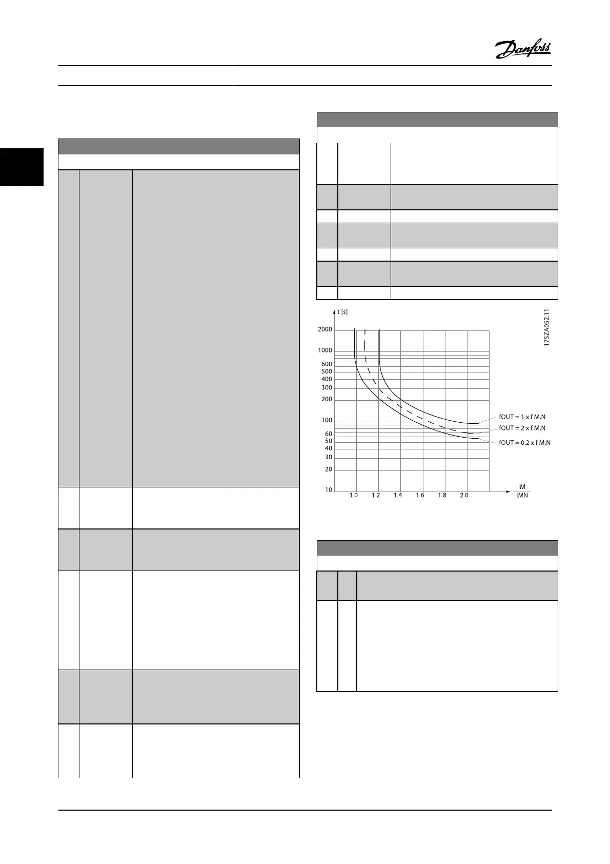
Figure 3.4 ETR profile
1-91 Motor External Fan
Option: Function:
[0]
*
No No external fan is required, i.e. the motor is derated at
low speed.
[1] Yes Applies an external motor fan (external ventilation), so
that no derating of the motor is required at low speed.
The upper curve in graph above (fout = 1 x fM,N) is
followed if the motor current is lower than nominal
motor current (see 1-24 Motor Current). If the motor
current exceeds nominal current, the operation time still
decreases as if no fan were installed.
Parameter Descriptions FC 300 Programming Guide
3-24 MG.33.MA.22 - VLT
®
is a registered Danfoss trademark
3

 Loading...


