3.3.10 PTC Thermistor Connection
Motor protection can be implemented using a range of
techniques: PTC or KTY sensor (see also section KTY Sensor
Connection) in motor windings; mechanical thermal switch
(Klixon type); or Electronic Thermal Relay (ETR).
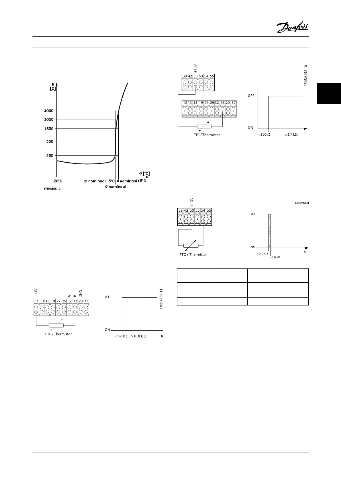
Using a digital input and 24 V as power supply:
Example: The adjustable frequency drive trips when the
motor temperature is too high.
Parameter set-up:
Set 1-90 Motor Thermal Protection to Thermistor Trip [2]
Set 1-93 Thermistor Source to Digital Input [6]
Using a digital input and 10 V as power supply:
Example: The adjustable frequency drive trips when the
motor temperature is too high.
Parameter set-up:
Set 1-90 Motor Thermal Protection to Thermistor Trip [2]
Set 1-93 Thermistor Source to Digital Input [6]
Using an analog input and 10 V as power supply:
Example: The adjustable frequency drive trips when the
motor temperature is too high.
Parameter set-up:
Set 1-90 Motor Thermal Protection to Thermistor Trip [2]
Set 1-93 Thermistor Source to Analog Input 54 [2]
Input
Digital/analog
Supply Voltage Threshold
Cut-out Values
Digital 24 V
< 6.6 kΩ - > 10.8 kΩ
Digital 10 V
< 800Ω - > 2.7 kΩ
Analog 10 V
< 3.0 kΩ - > 3.0 kΩ
NOTE!
Ensure that the chosen supply voltage follows the specifi-
cation of the thermistor element utilized.
Parameter Descriptions FC 300 Programming Guide
MG.33.MA.22 - VLT
®
is a registered Danfoss trademark 3-25
3

 Loading...


