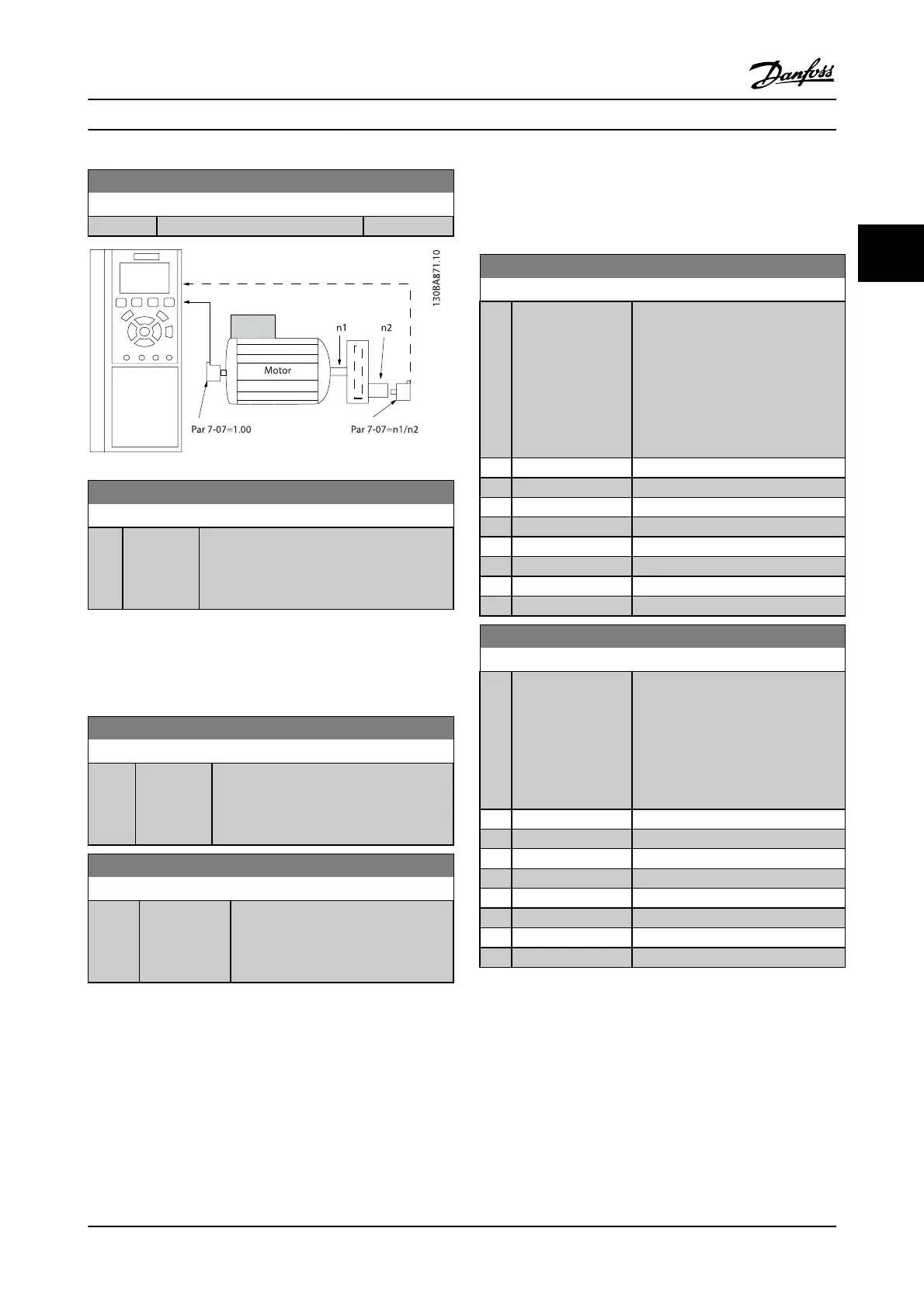
7-07 Speed PID Feedback Gear Ratio
Range: Function:
1.0000
*
[Application dependant]
7-08 Speed PID Feed Forward Factor
Range: Function:
0 %
*
[0 - 500 %] The reference signal bypasses the speed
controller by the amount specified. This
feature increases the dynamic performance of
the speed control loop.
3.9.2 7-1* Torque PI Control
Parameters for configuring the torque PI control in torque
open-loop (1-00 Configuration Mode).
7-12 Torque PI Proportional Gain
Range: Function:
100 %
*
[0 - 500 %] Enter the proportional gain value for the
torque controller. Selection of a high value
makes the controller react faster. Too high a
setting leads to controller instability.
7-13 Torque PI Integration Time
Range: Function:
0.020 s
*
[0.002 - 2.000
s]
Enter the integration time for the torque
controller. Selecting a low value causes
the controller to react faster. Too low a
setting leads to control instability.
3.9.3 7-2* Process Ctrl. Feedb.
Select the feedback sources for the process PID control, and
the way in which this feedback should be handled.
7-20 Process CL Feedback 1 Resource
Option: Function:
The effective feedback signal is made
up of the sum of up to two different
input signals.
Select which adjustable frequency
drive input should be treated as the
source of the first of these signals. The
second input signal is defined in
7-22 Process CL Feedback 2 Resource.
[0]
*
No function
[1] Analog input 53
[2] Analog input 54
[3] Frequency input 29
[4] Frequency input 33
[7] Analog input X30/11
[8] Analog input X30/12
[15] Analog Input X48/2
7-22 Process CL Feedback 2 Resource
Option: Function:
The effective feedback signal is made
up of the sum of up to two different
input signals. Select which adjustable
frequency drive input should be
treated as the source of the second of
these signals. The first input signal is
defined in par. 7-21.
[0]
*
No function
[1] Analog input 53
[2] Analog input 54
[3] Frequency input 29
[4] Frequency input 33
[7] Analog input X30/11
[8] Analog input X30/12
[15] Analog Input X48/2
Parameter Descriptions FC 300 Programming Guide
MG.33.MA.22 - VLT
®
is a registered Danfoss trademark 3-77
3

 Loading...


