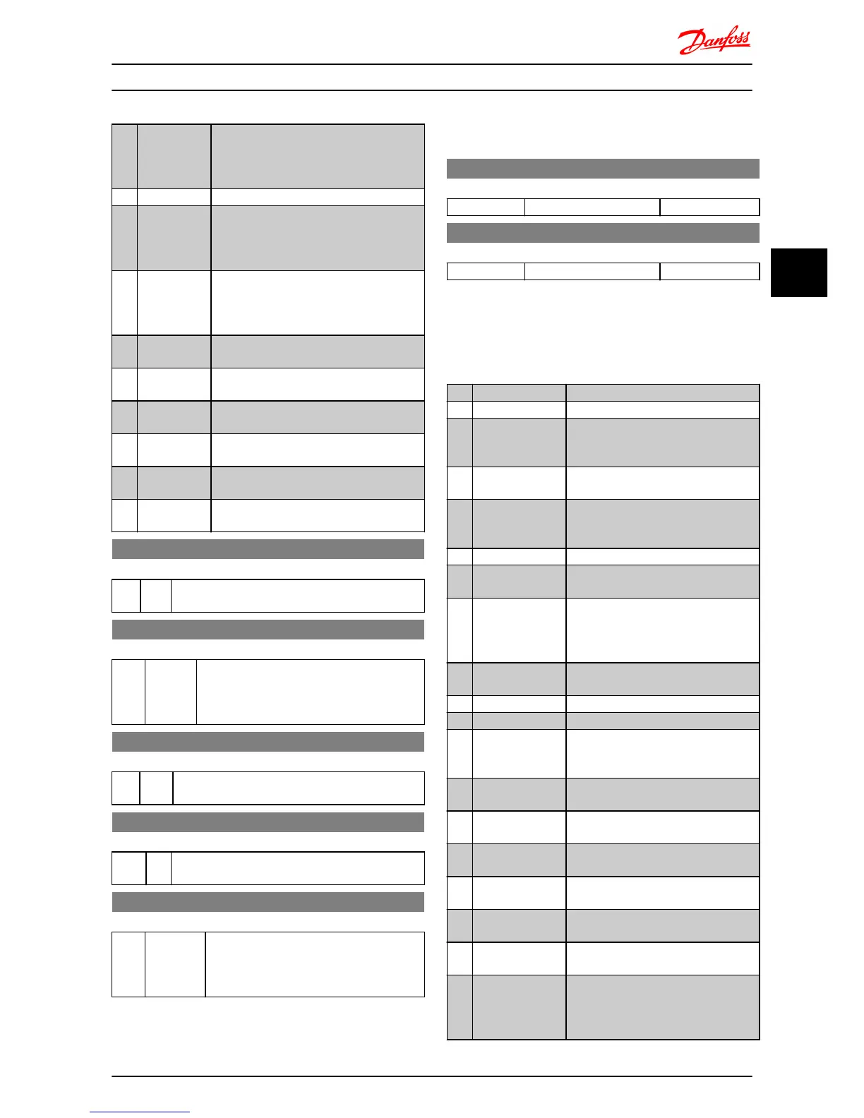
[28] Catch up Select Catch up/Slow down to increase or
reduce the resulting reference value by the
percentage set in 3-12 Catch Up/Slow Down
Value
[29] Slow down Same as Catch up [28]
[32] Pulse input
(only terminal
33)
Select Pulse input when using a pulse
sequence as either reference or feedback.
Scaling is done in parameter group 5-5*
Pulse Input
[34] Ramp bit 0
Logic 0=Ramp1, see parameter group 3-4*
Ramp1
Logic 1=Ramp2, see parameter group 3-5*
Ramp2.
[60] Counter A
(up)
Input for counter A.
[61] Counter A
(down)
Input for counter A.
[62] Reset counter
A
Input for reset of counter A.
[63] Counter B
(up)
Input for counter B.
[64] Counter B
(down)
Input for counter B.
[65] Reset counter
B
Input for reset of counter B.
5-10 Terminal 18 Digital Input
Option: Function:
[8] * Start Select function from available digital input range.
See parameter group 5-1* Digital Inputs for choices.
5-11 Terminal 19 Digital Input
Option: Function:
[10] * Reversing Select function from available digital input
range.
See parameter group 5-1* Digital Inputs for
choices.
5-12 Terminal 27 Digital Input
Option: Function:
[1] * Reset Select function from available digital input range.
See parameter group 5-1* Digital Inputs* for choices.
5-13 Terminal 29 Digital Input
Option: Function:
[14] * Jog Select function from available digital input range.
See parameter group 5-1* Digital Inputs for choices.
5-15 Terminal 33 Digital Input
Option: Function:
[16] * Preset bit 0 Select function from available digital input
range.
See parameter group 5-1* Digital Inputs for
choices.
4.6.3 5-3* Digital Outputs
5-34 On delay, Terminal 42 Digital Output
Range: Function:
0.01 s* [0.00-600.00 s]
5-35 Off delay, Terminal 42 Digital Output
Range: Function:
0.01 s* [0.00-600.00 s]
4.6.4 5-4* Relays
Parameter group for configuring timing and output
functions for relays.
[0] No Operation Default for all digital and relay outputs.
[1] Control Ready Control board receives supply voltage.
[2] Drive Ready Frequency converter is ready for
operation and applies supply signal on
control board.
[3] Drive Ready,
Remote
Frequency converter is ready for
operation in Auto On-mode.
[4] Enable/No
Warning
Frequency converter is ready for
operation. No start or stop command is
given. No warnings are present.
[5] Drive Running Motor is running.
[6] Running/No
Warning
Motor runs, and no warning are
present.
[7] Run in Range/No
Warning
Motor runs within programmed current
ranges, see 4-50 Warning Current Low
and 4-51 Warning Current High. No
warnings are present.
[8] Run on ref/No
Warning
Motor runs at reference speed.
[9] Alarm An alarm activates output.
[10] Alarm on Warning An alarm or warning activates output.
[12] Out of Current
Range
Motor current is outside range set in
4-50 Warning Current Low and 4-51
Warning Current High.
[13] Below Current,
low
Motor current is lower than set in 4-50
Warning Current Low.
[14] Above Current,
high
Motor current is higher than set in 4-51
Warning Current High.
[16] Below Frequency,
low
Motor speed is lower than set in 4-40
Warning Frequency Low.
[17] Above Frequency,
high
Motor speed is higher than set in 4-41
Warning Frequency High.
[19] Below Feedback,
low
Feedback is lower than set in 4-56
Warning Feedback Low.
[20] Above Feedback,
high
Feedback is higher than set in 4-57
Warning Feedback High.
[21] Thermal Warning Thermal warning is present when
temperature exceeds limit in motor,
frequency converter, brake resistor or
thermistor.
Parameter Descriptions
VLT
®
Micro Drive FC 51 Programming Guide
MG02C602 - VLT
®
is a registered Danfoss trademark 29
4 4

 Loading...


