In a few systems load sensing pump pressure may result in unstable adjustment of the oil flow and a
tendency towards system hunting.
This may be the case with working functions that have a large moment of inertia or over-center valves. In
such systems main spools for pressure control can be advantageous.
PVBS, main spools for pressure control
The spools are designed in such a way that the pump pressure is controlled by the spool travel. The main
spool must be displaced until the pump pressure just exceeds the load pressure before the working
function is applied. If the main spool is held in this position, the pump pressure will remain constant –
even if the load pressure changes – giving a stable system.
The use of pressure control spools, however, also means that:
•
the oil flow is load dependent
•
the dead band is load dependent
•
the pump pressure can exceed the load pressure by more than is usual
•
the pressure drop across main spool varies (energy consumption)
Due to these factors it is recommended that pressure control spools are only used when it is known for
certain that problems with stability will arise or already have arisen, and in applications where constant
pressure is needed e.g. drill holding.
Background
Instability in load sense control systems in certain applications with oscillations in the range of 1/2 - 2 Hz
can cause severe instability problems while trying to control functions in an application.
Critical applications are usually related to functions with an important inertia torque and/or functions
with secondarily fitted pressure controlled components e.g. over-center valves.
Examples:
•
a slewing function
•
main lifting/lowering function of a crane
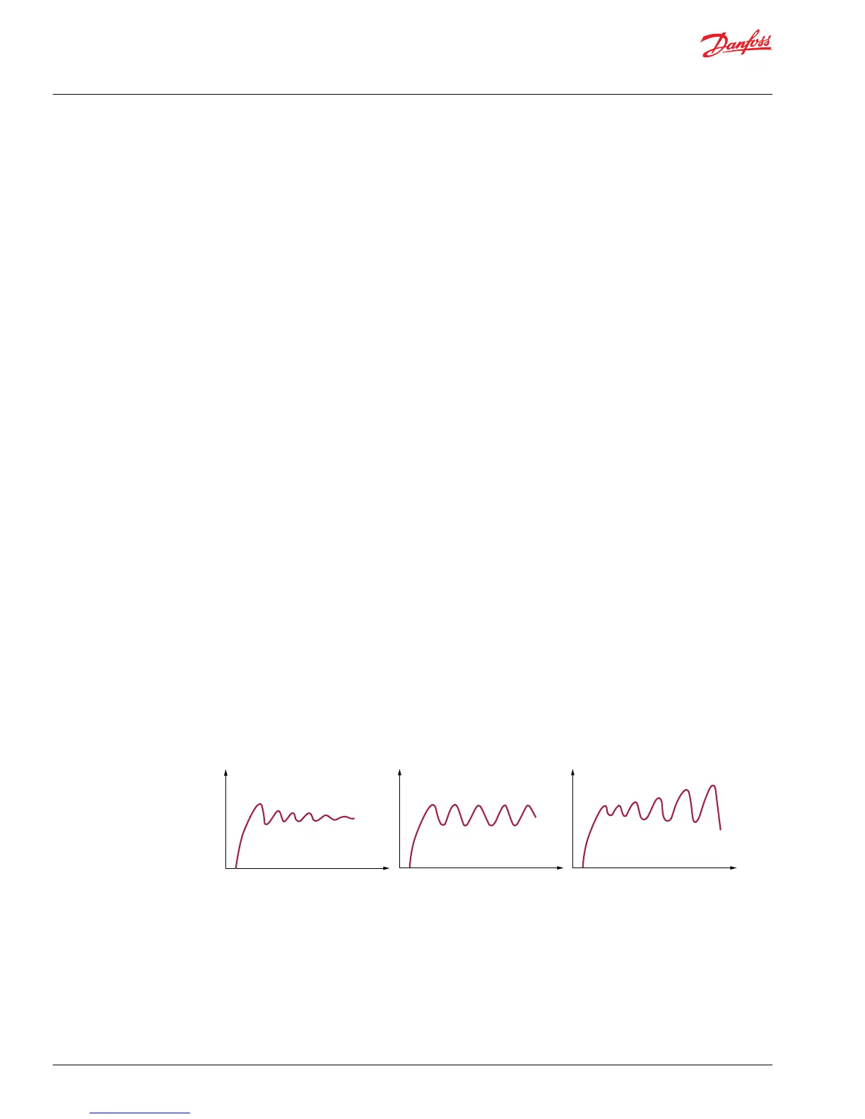
The problem usually manifests itself in prolonged oscillation phenomena (Fig. 1), in a relatively constant
sequence of oscillations (Fig. 2) or in the worst case in an amplified sequence of oscillations (Fig. 3).
Fig. 1 Prolonged sequence Fig. 2 Constant sequence Fig. 3 Amplified sequence
To control the oscillation phenomena the "pressure control spool" was developed and is a patented
system which can minimize most of the oscillation issues.
Principle
The idea was to create a system operating independently of a constantly changing load pressure.
Therefore, we changed the well-known LS principle (Fig. 4), so that compensated pump pressure is part
of the LS system (Fig. 5) after the pressure compensator and before the metering range of the main spool.
Upon actuation of the spool, it will be led via a fixed and a variable orifice.
Technical Information
PVG 32 Proportional Valve Group
Function
22 |
©
Danfoss | August 2017 520L0344 | BC00000038en-US0802

 Loading...


