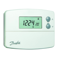
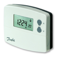
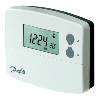
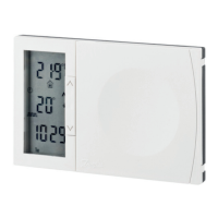
TP5001
8
GR
TR
LV
LT
UA
RU
GB
IMPORTANT - To ensure that the factory programmes are set
and the micro-computer is operating correctly it is essential
that you press and hold the RESET button before you begin any
commissioning or programming.
Models with remote sensor inputs
Terminal block for remote control/sensing
is located on the circuit board above the
battery compartment.
RX1
RX2 & RX3
12
3
4
ELECTRONICS
N
L
COM
ZONE
1 ON
ZONE
1 OFF
A
ELECTRONICS
B
C1
2
345
6
N
L
ZONE
1 ON
ZONE
1 OFF
ZONE
2 ON
ZONE
3 ON
COM
TERMINAL 6
RX3 ONLY
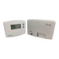
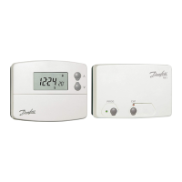
3.3 RX Receiver Wiring (RF models only)
1) For mains voltage operated systems link terminal 2 to mains live supply.
2) Power supply to unit must not be switched by timeswitch.
S1/D
S2/E
S1/D
S2/E
Window or
teleswitch
contact
(NO or NC)
Teleswitch
contact (NC)
Window
contact (NC)
S1/D
S2/E
Con gured for
remote room
sensor or limit
sensor
Con gured for
window contact or
other contact such
as teleswitch
Con gured for
window contact
and other contact
such as teleswitch