Page 28 of 108
M-AP-001-EN Rev. N
M-AP-001-EN Rev. N
Control Interface Wiring
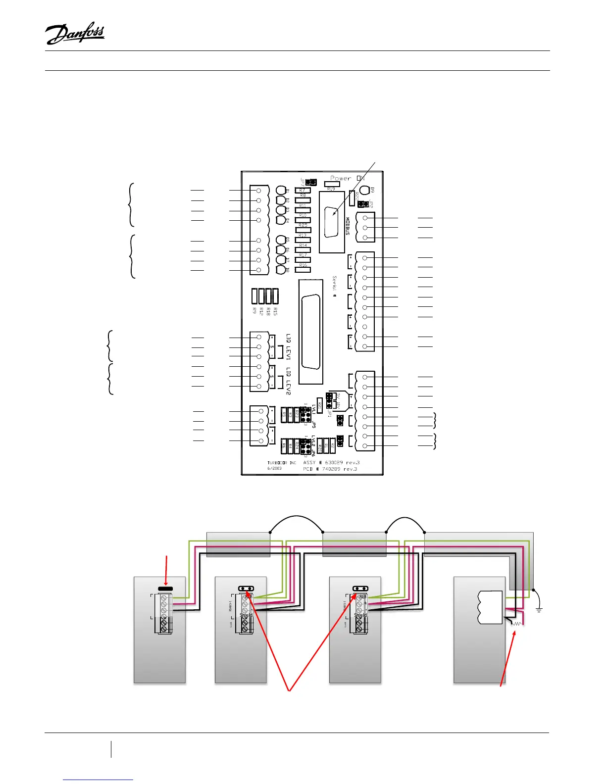
The Compressor I/O Board is the entry point for control wiring from the chiller/plant to the
compressor. Refer to Figures 4-1 and 4-2 for the proper Compressor I/O Board connectivity.
Figure 4-1 - Typical Control
Wiring
OUT
I/O
I/O
IN
IN
IN
IN
OUT
OUT
OUT
OUT
IN
IN
OUT
OUT
OUT
OUT
IN
IN
IN
IN
ModBus Common (Shield)
ModBus RS-485 NetB
ModBus RS-485 NetA
Demand + 0-10V
Demand -
Interlock Contact - Safety N/C
Interlock Contact - Safety N/C
Compressor Status - N/O Contact
Compressor Status - N/O Contact
Entering Chilled Water
Temp. Sensor
Leaving Chilled Water
Temp. Sensor
EXV Phase 1A
EXV Phase 1B
EXV Phase 2A
EXV Phase 2B
EXV #1
(Evaporator or
load balancing
valve)
EXV Phase 1A
EXV Phase 1B
EXV Phase 2A
EXV Phase 2B
EXV #2
(Economizer or
load balancing
valve)
Level Sensor +15V
Sensor Signal , 1-5Volts
Level Sensor 0V
Level Sensor +15V
Sensor Signal , 1-5Volts
Level Sensor 0V
Level
Sensor
#1 (Evaporator)
Level
Sensor
#2 (Economizer)
Liquid Temperature +
Liquid Temperature -
Compressor Running - N/O Contact
Compressor Running - N/O Contact
Pressure Sensor Signal, 1-5Volts
Sensor +5V
Sensor 0V
Temperature Sensor Signal, 1-5Volts
*Universal Analog Output +
*Universal Analog Output -
* Universal output can be used for :
output manual control
0-5VDC or 0-10VDC
RS232 Monitoring Connector (DB9)
J6
J7
J1
J2
J4 J5
J3
J8
LIQDT
SPEED
STATUSI/LOCK
DEMAND
COM
NETA
NETB
EXV1
EXV2
1A 1B 2A 2B 1A 1B 2A 2B
OUT
OUT
OUT
OUT
OUT
OUT
OUT
OUT
OUT
OUT
OUT
OUT
IN
IN
IN
OUT
IN
OUT
RUN
ENTRY LEAVE
ANALOG
Float
Float
SPARE T SPARE P
No function
No function
**Level sensor circuit can be congured
for two types of sensors using jumpers
JP5 and JP6. Refer to the Installation and
Operations Manual for details.
4 Control Interface Wiring
RS485-1
I-Lock
CIM Board
RS485-1
I-Lock
CIM Board
RS485-1
I-Lock
CIM Board
REF
+
-
Shield
REF
+
-
Shield
REF
+
-
Shield
REF
-
+
120Ω
PLC
COM NETB NETA
MODBUS
Retain
Termination
Jumper in
Last Board
Remove Termination
Jumper in All
Intermediate Boards
Termination Resistor should only be included
if one is not included in the PLC. If the PLC
has a resistor installed, do not add an addi-
tional one. If the PLC does not have a resistor
installed, then one should be installed.
Figure 4-2 - ModBus
Grounding Diagram

 Loading...


