38
VLT
®
Series 3500
The following must be programmed:
Function Parameter # Parameter Value Data Value #
Safety interlock 003 KEY HOA w. stp [1]
Power Up Mode 014 Stopped in local operation, [1]
using saved reference speed
Minimum frequency 201 18 Hz
Maximum frequency 202 60 Hz
START 402 LATCH START [1]
STOP 404 STOP [4]
0-I
MAX
407 I
MAX
0-20 mA [25]
Reference 412 0-10 V DC [1]
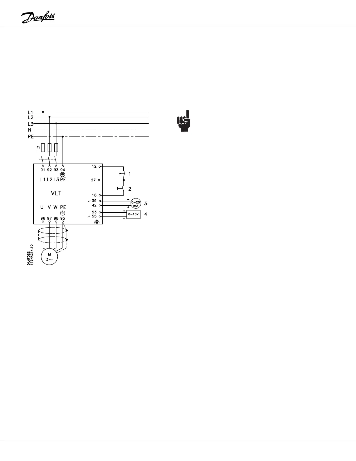
NOTE:
A shield for control wires is to be connected in
accordance with the installation instructions.
All settings are based on factory settings.
Be sure to check the motor data settings (parameters
104, 105 and 107, or the Quick Setup menu items 1, 2
and 3). They must be set based upon the actual motor
used.
1 = Stop
2 = Start
3 = 0 to 20 mA output signal (0-I
MAX
)
4 = 0 to 10 V control signal (0-100% speed)
External safety interlocks can be connected between
terminals 12 and 27.
Example 4:
Although three-wire “Start/Stop” is not commonly used for
unattended operation, some installations may require it
for operator safety.
A pump is to be controlled by means of a 0 to 10 V
control signal, corresponding to 18 to 60 Hz.
"Start/Stop" is to be in the form of a three wire (no auto-
restart) "Start/Stop".
A remote indication of output current is required. The
signal for that is to be 0 to 20 mA.
 Loading...
