39
VLT
®
Series 3500
Example 5:
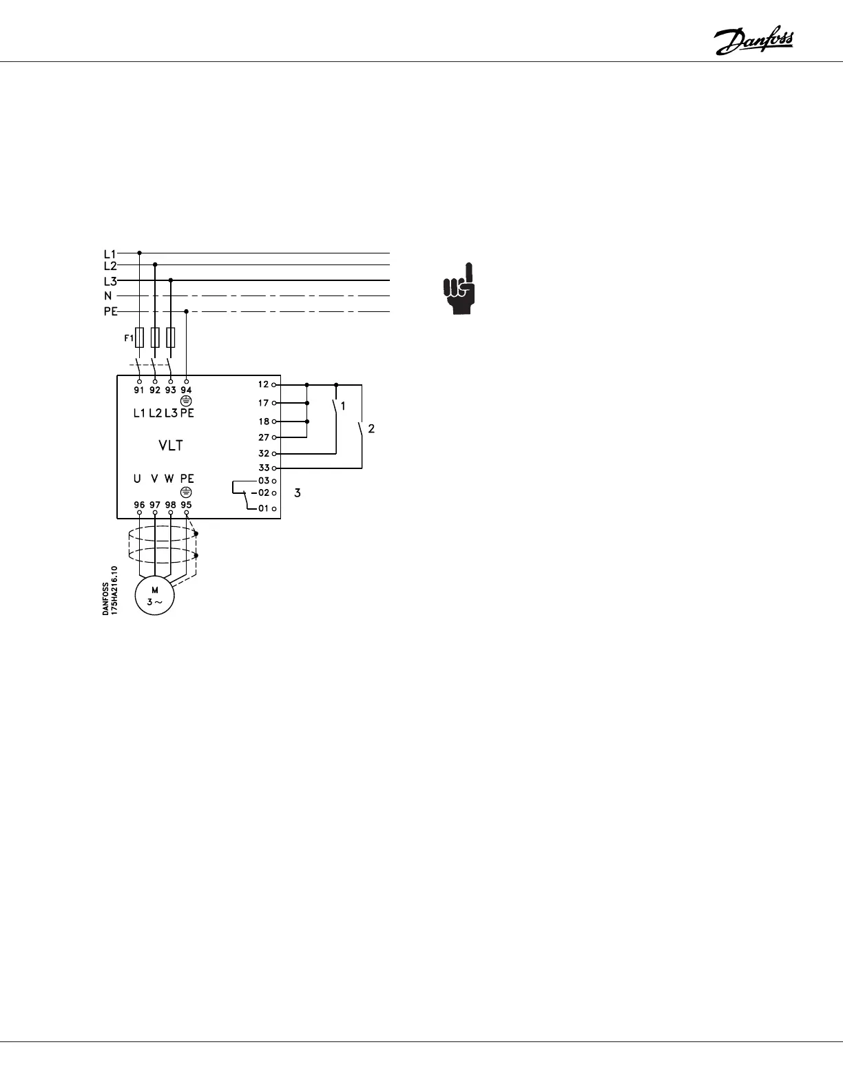
The output frequency of the drive is to be controlled by
means of digital signals from a PLC or floating point
control. Whenever the output frequency is outside the 10
to 45 Hz range, the relay output is to be activated giving
a signal to the PLC.
NOTE:
A shield for control wires is to be connected in
accordance with the installation instructions.
All settings are based on factory settings.
Be sure to check the motor data settings (parameters
104, 105 and 107, or the Quick Setup menu items 1, 2
and 3). They must be set based upon the actual motor
used.
1 = Speed up
2 = Speed down
3 = Relay is activated when the output frequency is
outside the 10 to 45 Hz range by closing 01-02.
External safety interlocks can be connected between
terminals 12 and 27.
The following must be programmed:
Function Parameter # Parameter Value Data Value #
Safety interlock 003 KEY HOA w. stp [1]
Minimum frequency 201 0 Hz
Maximum frequency 202 60 Hz
Frequency too low 210 10 Hz
Frequency too high 211 45 Hz
Speed up and down 401 FREEZE REF. [2]
Speed up and down 406 SPEED UP/DOWN [1]
Frequency warning on relay 409 OUT FREQ RGE [11]
 Loading...
