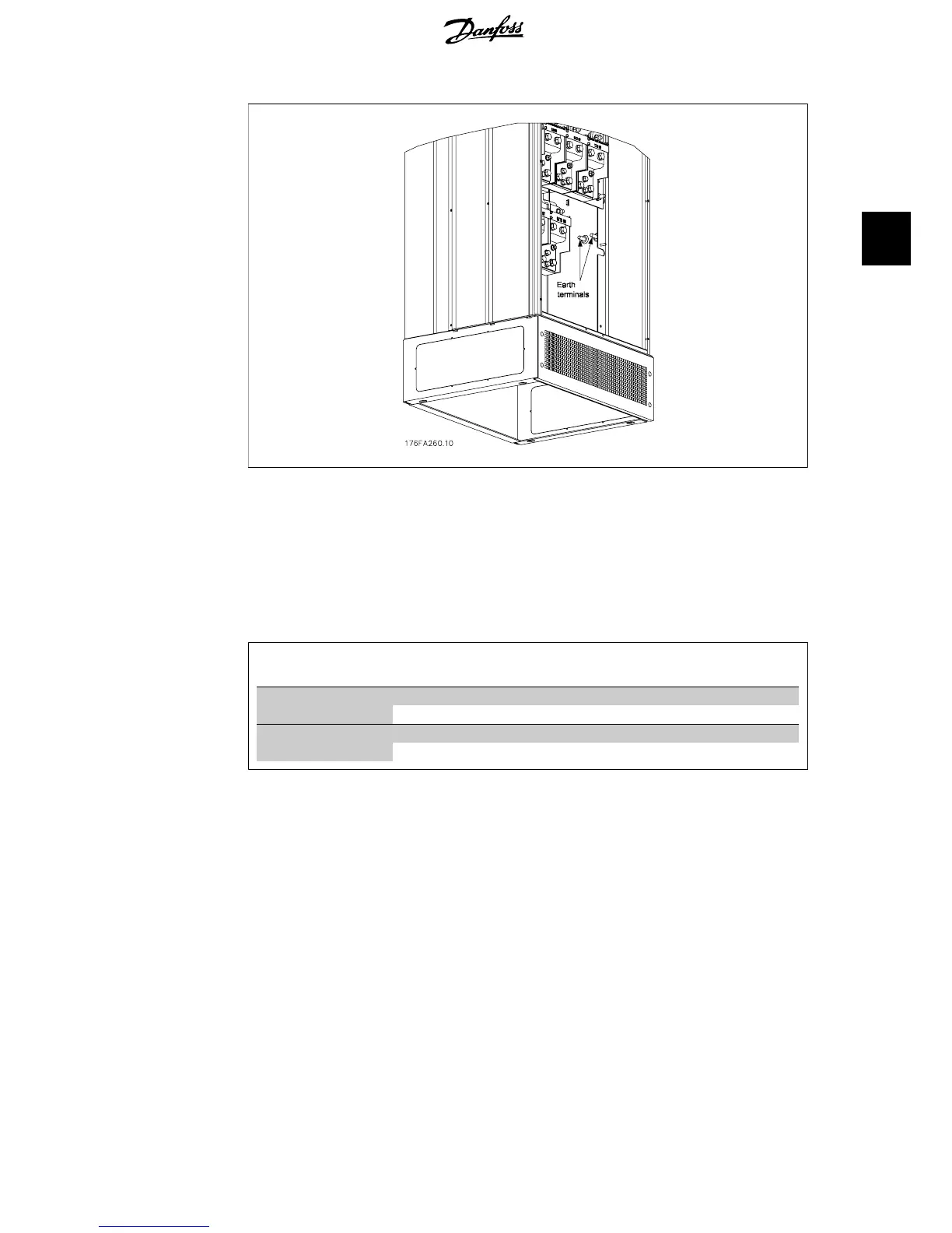
Illustration 3.15: Position of earth terminals IP21 (NEMA type 1) and IP54 (NEMA type 12)
Cooling
Cooling can be obtained in different ways, by using the cooling ducts in the bottom and the top
of the unit, by using the ducts in the backside of the unit or by combining the cooling possibilities.
Airflow
The necessary airflow over the heat sink must be secured. The flow rate is shown below.
Enclosure Door fan / Top fan air-
flow
Airflow over heatsink
IP00 / Chassis D1 and D2
255 m
3
/h (150 cfm) 765 m
3
/h (450 cfm)
E1
255 m
3
/h (150 cfm) 1444 m
3
/h (850 cfm)
IP21 / NEMA 1
IP54 / NEMA 12
D1 and D2
170 m
3
/h (100 cfm) 765 m
3
/h (450 cfm)
E1
340 m
3
/h (200 cfm) 1444 m
3
/h (850 cfm)
Table 3.2: Heat Sink Air Flow
VLT
®
5000/6000/8000
High Power Installation Guide
3. Installation
MI.90.J2.02 - VLT
®
is a registered Danfoss trademark
17
3
 Loading...


