VLT® 7000 Booster
Description of choice:
Disable the pump or pumps that needs to be taken out
of operation. Please be aware that removing pumps
can make it impossible for the remaining pumps to
keep up the system pressure at the desired level.
■ Quick Menu 35 Par. 720 Pump running hours
Par. 720 Pump running hours
(PUMP RUN. HOURS)
Value:
0.0 hours - 999999.9 hours
Function:
As described in the beginning of this document, it
is possible to choose modes, where staging and
destaging is determined by the running hours of the
pumps (LRHIMRHO). In this parameter it is possible
to adjust the recorded running hours.
Please note, that the AUX pump will be no. 8 in the
display of the LCP, even if it is pump no. 7 in the system.
Description of choice:
Adjust the running hours of the pumps.
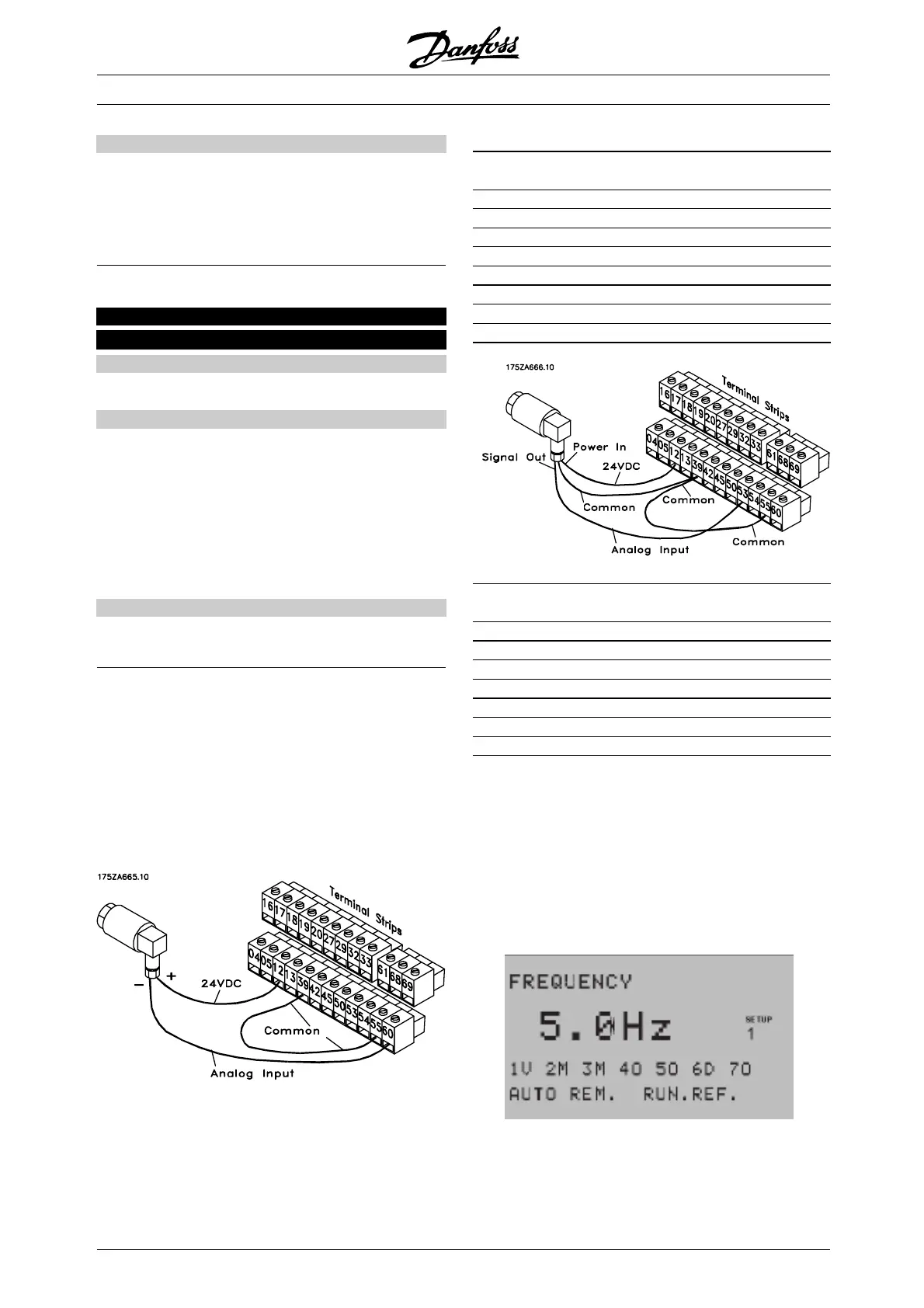
■ Feedback transmitter wiring
Terminal 12 and 13 of the VLT provide access to a
24 VDC, 200 mA power supply. This can be used
to power remote transmitters, so an external power
supply is generally not needed. The diagrams below
show how to wire two- and three-wire transmitters.
Single 4 - 20 mA feedback transmitter
connection (default setting)
Programming:
Parameter Parameter Parameter
Number Description Value
415 Ref./FDBK UNIT Process unit
413 MIN. FEEDBACK Transmitter low limit
414 MAX. FEEDBACK Transmitter high limit
308 AI [V] 53 FUNCT. NO OPERATION
311 AI [V] 54 FUNCT. NO OPERATION
314 AI [mA] 60 FUNCT. FEEDBACK
315 AI 60 SCALE LOW 4 mA
316 AI 60 SCALE HIGH 20 mA
Programming:
Parameter Parameter Parameter
Number Description Value
415 Ref./FDBK UNIT Process unit
413 MIN. FEEDBACK Transmitter low limit
414 MAX. FEEDBACK Transmitter high limit
308 AI [V] 53 FUNCT. FEEDBACK
309 AI 53 SCALE LOW 0 V
310 AI 53 SCALE HIGH 10 V
314 AI [mA] 60 FUNCT NO FUNCTION
In the display line 3 in the LCP the user is given
information on which pumps are running and
which one is the lead pump.
Ifthesystemcontainsmorethan4pumpsthestatus
is like in the below example which shows a system
with fixed lead pump containing 7 pumps in total. That
means 1-7 indicates the pump numbers.
176FA211.10
When up to 4 pumps are available, the pump
number is also shown:
MG.70.A1.02 - VLT is a registered Danfoss trademark
108
 Loading...